How I Ensure Reliability or, I Did it My Way!
Who am I?
- I am Brian E. Eves, known to some exhibitors of S4N as Alec Trician.
- Retired after working in Signal Engineering for 45 years.
- Started with BR at Edge Hill, Liverpool.
- Moved to the Eastern Region in the mid 1980’s .
- Survived privatization with Jarvis and completed 15 years with Network Rail.
- Been involved with S4N since the early days of Holmfield House, usually supplying the power to layouts and stands.
Layouts Wired
- Plemsworth CLC, Merseyside MRC 1983 – 1986
- Whetstone GCR, Andy Gibbs, 1987 – 1990’s
- Dewsbury GNR, Geoff Tiffany, Dave Carter, Me, 1988 to date
- Grimsby Loco, GCR, Ian Clark, 2019ish
- Flockton Sidings, Dave Carter, 2021
- Rewires undertaken
- Breton Mill, Dave Carter, 1990’s
- Grimsby Town (?), GCR, Ian Clark, 2010’s
My Reasoning behind my method
- To provide faultless running for exhibition layouts for the paying public.
- To prevent frustration to operators caused by intermittent failures.
- To ensure exhibition layouts suffer no damage to wiring during transportation.
- To use the skills learnt from 45 years of working in railway signalling.
- To prevent “She who must be obeyed” kicking me from under her feet.
My Methods
- Planning
- Agreement with partners in the project
- Tools
- Materials
- Documentation
- Wiring strategy
Planning and Agreement
- Decide what you are building
- Decide upon traffic movements
- Decide upon infrastructure required to meet traffic movements
- Think where points, signals and other infrastructure is positioned in relation to your baseboards
- Make allowances for wiring in your baseboard construction
- Decide upon testing strategy and how you record it
- Document your decisions
Tools
- A good soldering iron or two, with holder and cleaning sponge
- Wire strippers of your choice. I like the sort that hold the insulation as you strip the wire (See my favourite stripper)
- Wire cutters, small for getting into tight spaces and normal 6 inch for general work
- Pliers for holding wires so you don’t burn your fingers
- Screwdrivers of various types and sizes
- Multimeter, either digital or analogue, with test leads
- A simple battery with bulb or buzzer for quick testing
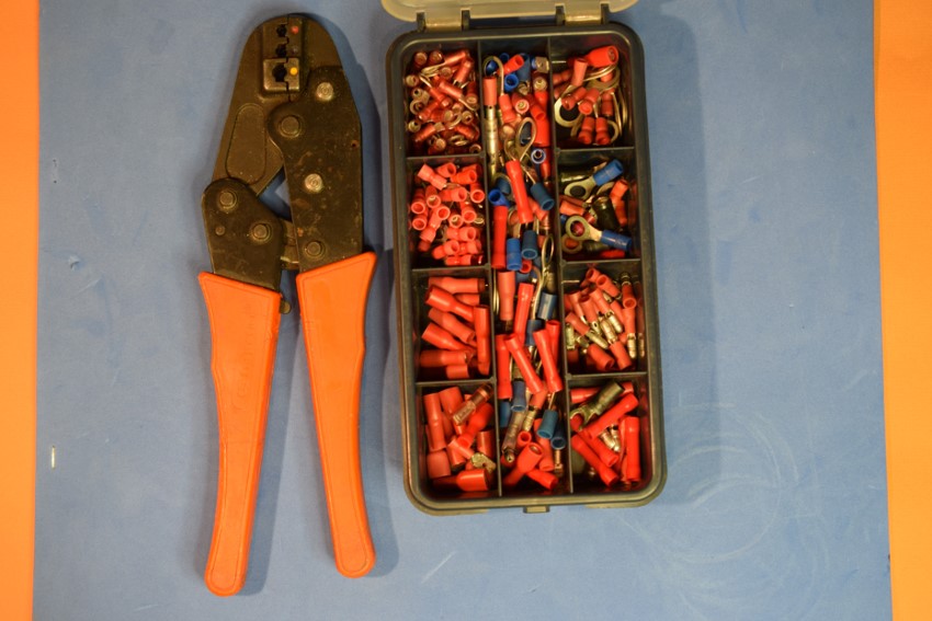
- Crimping tools for screw connectors
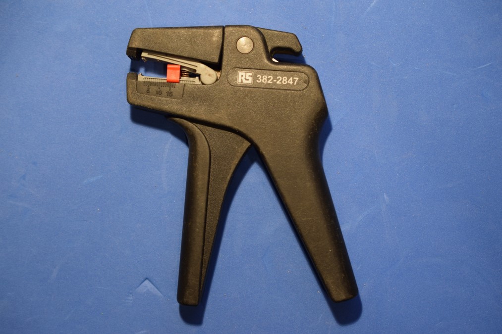
My favourite Stripper
- The wire is inserted between the jaws and the handle squeezed.
- The outer sheath is held between the black jaws
- As the handle is squeezed the grey coloured jaws pull the sheath off
- Length of stripping can be set by moving the red stopper
- Mostly I strip about 5mm for soldering
- Stripping to much can lead to cross connections
- There is a wire cutter on the back of the tool, above the RS number
Multimeters
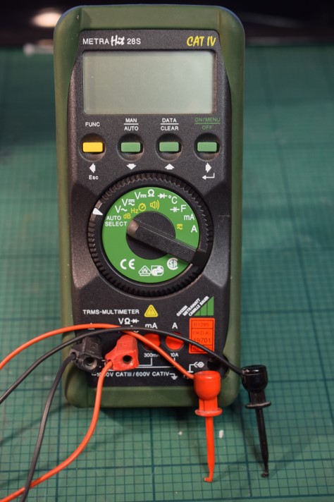

Test Leads

- Good quality test leads are required, always test before use
- 4mm shrouded plug fits into the meter
- Newer leads have a shroud over the probe tip (IEE Reg’s)
- Crock clip is a push fit on the probe, some have swappable probes and clips
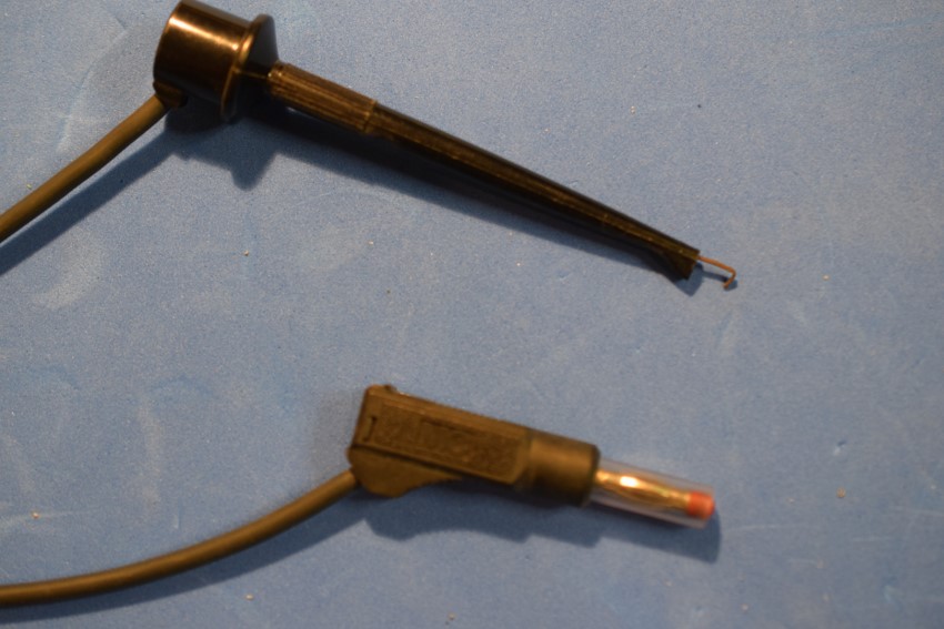
- Self made test lead, longer than bought in ones
- Hooked probe enables lead to be secured to small terminals
- Hook retracts into probe
- Meter plug has a retractable insulating sleeve
Crimping Tools

Materials – Dropper Wire
- Single strand solid wire
- Silver or silver plated for preference
- Between 0.5 and 1mm diameter
- Soldered direct to the underside of the rail, alternatively to the outside web of the rail
- Soldered to the rails before you stick it to your baseboard.
- A dropper upon each end will ensure reliability
Materials – Wire
- Multistrand wire is essential in my opinion, differing sizes for different uses (Single strand like network or telephone wire is prone to breakage if knocked)
- Traction, I use 0.75mm²; 9/0.30 Two cores twisted together using an electric drill
- Supply for point motors, modules, etc.. 0.5mm²; 16/0.2
- Switched circuits, 0.2mm²; 7/0.2
- Controller Bus, e.g. Express-Net, 0.2mm²; 7/0.2 multicore alarm/mic cable. Get screened cable if affordable
- A good source of colour coded wire for switched circuits is parallel printer cable
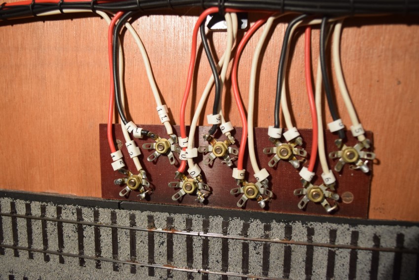
Connectors for Dropper Wires
- Star Tags; Acquired from Eileen’s Emporium (When Eileen was Eileen)
- Secured by a screw through the centre hole
- Fingers can be bent up to clear other tags or equipment
- Cleaned and tinned before fitting to the baseboard
- Tinned wire end or dropper laid along the finger and soldered
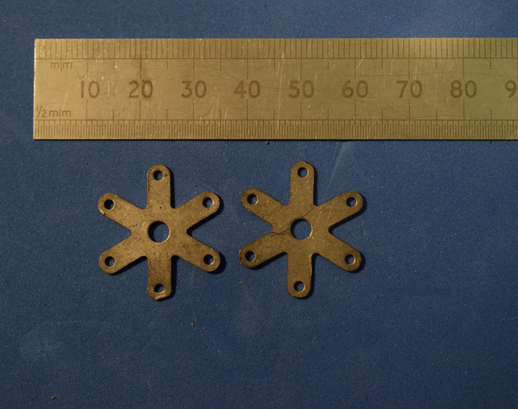
- Solder Eyelet; 3 contact with mounting hole, roughly 22mm across, Farnell Electronics (CPC is their retail branch) stock No 2691424
- Can be doubled up but solder together
- Solder tinned wire along the finger or poke it through
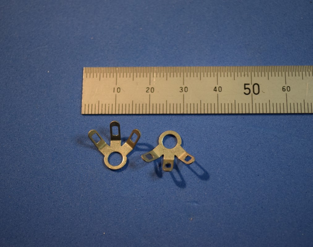
- Bus Terminal Tags, DCC Concepts, 3 contacts with mounting hole
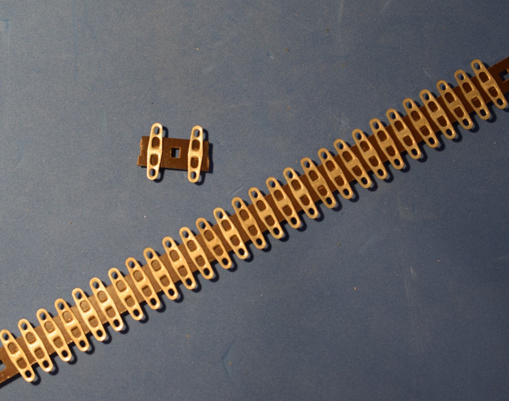
- RS Barrier Strip:
- 28 contacts 6.3mm Pitch, single row, RS Stock No 433-781
- Can be cut into required length and contacts removed
- For rail panels cut into pieces of three and remove the centre contact and use hole for mounting screw
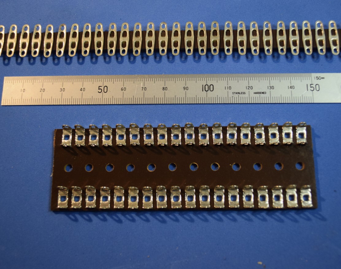
- Two types for Barrier Strip are sold by RS
- I’ve use the 28 way for dropper connections,
- Termination for inter-board connector, connections to point motors and signal modules
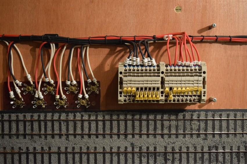
- The 36 way, RS No 433-703,has two rows
- I’ve used these for termination point where multiple wires go to supply bus’s
- I solder a piece of wire down the centre of each row and then connect to the fingers
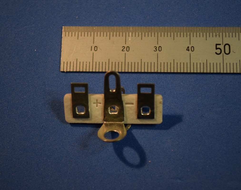
- Section of 36 way Barrier Strip cut in half and used as a connection point for devices that required a 12V supply.
- Feeder wires in and out are at the base
Materials- Baseboard Connectors used on Dewsbury
- SMS Qikmate range of connectors in several configurations allowing the use of crimped pins and sockets of differing wire sizes. See Farnell Electronics stock No 535850 (See Data Sheet SMS Series)
- Dewsbury has SMS Qikmate for their inter-baseboard and are populated with several differing diameters of wire which are encased in expandable sleaving, such as RS Stock No 408-215: It a bit like the old finger lock toy, push it together it expands, pull it apart it contracts. Heat shrink tubing finished the ends off nicely.
- The baseboard end is secured with a clamp, a terry clip is used for securing the plug end when in transport
- The inter-connect wires are soldered to a 28 way barrier strip, giving a handy test point if required
- Cannon D Type of various contact arrangements; 9, 15, 25, 37 or 50 way. Dewsbury uses a pair of 50 way D Type between the layout and the signalling panel. (quite small an can be difficult to solder)
- 5 Pin DIN type connectors used for the LENZ DCC handsets
- Some DCC handsets use the RJ type of plug and socket, the type used for LAN and phone connections


- One of the connectors on Dewsbury
- It shows the plug end and the encased wiring with different diameters of wire.
- They are soldered to the Barrier Strips
- Cable end retention Terry Clip not yet installed
- Expandable sleeving used to form into a cable
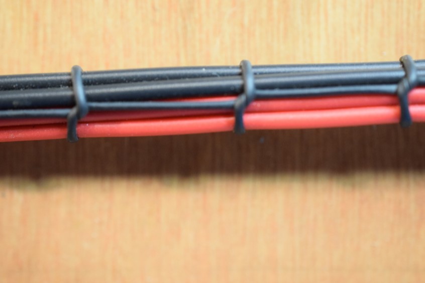
Materials: Cable / Wire Management
- Lacing cord; e.g. Black PVC 0.75mm, RS Stock No 554080
- Other types available from RS and others
- Ty-Wraps; available from everywhere, Aldi, B&Q, Liddle etc.. Different sizes and colours available
- Cable Tie Mount; keeps wires and looms secured to the baseboard; e.g. Farnell Stock Code 1015672; available elsewhere
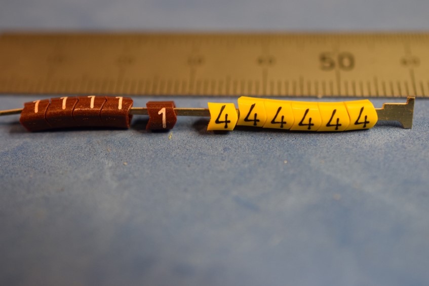
- Spiral Wrap; e.g. Farnell Stock Code 1416083 •Cable markers of various sizes
- Expandable sleeving, such as RS Stock No 408-215
Documentation 101
- Draw your layout on whatever medium suits you. I use AutoCad but other CAD programs will suffice
- Start by drawing the baseboard outline and rails, if using CAD draw on one layer •Copy to another layer and colour rails to the polarity required, easy with DCC control.
- Drawings for Dewsbury have 15 layers that can be turned on or off as required
- Use differing colours for crossing (The correct term for the bits where rails cross, not the dreaded frog!)
- Once drawn out place tags and assign a unique number to the tags
- Where two individual rails meet in the same section, only one tag is required
- Print out copies to allow for marking off as testing progresses
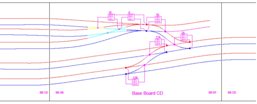
Documentation: Track & Signal Layers
Documentation: Crossing Feeds
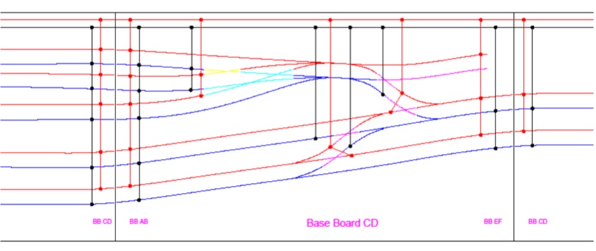
Documentation: DCC Section Feeds
Glossary
- Rail; A single length of whatever rail you’ve chosen with droppers at each end
- Rail Section; A length of one or more rails that form an electrical circuit connected to the Traction Bus at either end
- Track Panel; A constructed length track, be it plain line or point work
- Multiple Track Panels may form sections
- Tag; connection point for the dropper wire to connect to •Traction Bus; wires forming the supply from your controller / system
- Multistrand has several small diameter pieces of copper making up one conductor.
- Multicore has several insulated conductors making up the cable
Method 1: Before Laying the Track
- Solder droppers to rail ends for each rail before fixing track panel to baseboard
- Ensure dropper is long enough to reach the tag •Measure resistance between the two droppers. The reading should be under 1 ohm
- Testing Note 01
- When using any multimeter, switch to the lowest Resistance Range and touch the probe ends together. This gives the resistance of the leads. Some DMM’s have a REL function which when pressed negates the lead resistance.
Method 2: Soldering to Dropper Tags
- When all track is laid for that baseboard repeat resistance testing.
- Ensure where isolation is required it is there
- Ensure that the right dropper goes to the right tag
- If correct, solder dropper/s to the tag
- Resistance test at end of each rail section tag to tag and tag to rail
- Multiple droppers from one Crossings can go to the same tag
- When each board is completely soldered check to ensure continuity and isolation correct, mark up print out to record stage complete
- A simple tick and or a cross will do but be consistent
- If more than one person wiring use different colour pencil to mark off
- Its not a bad idea to initial and date your work on the drawing
Method 3: Diagram of Connections
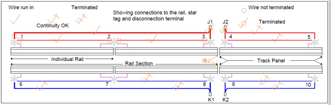
Diagram Explained
- Dropper soldered to one leg of tag or barrier strip connection
- For each rail section a wire runs through all tags for that section. Can run straight from tag to tag or follow in a loom with other wires (My preferred choice)
- With Star Tag or Solder Eyelet, wires soldered to separate legs
- Wires soldered to rail section ends routed to Traction Bus (J & K Bus for Lenz DCC system)
- IBJ: Insulated Block Joint; paper soaked in epoxy resin and inserted between rail section ends, cut and filed to shape when dry
Method 4: Wiring
- At least two different methods have been used over the years
- Wiring straight to the baseboard or
- Using a piece of peg board, painted white with the position of the tags, point motors and other infrastructure requiring wiring marked on in pencil. Cable ties or wire forming loops where wires are to run
- Each has its merits and challenges
- Use some form of cable markers to identify which tag / terminal the wire goes to
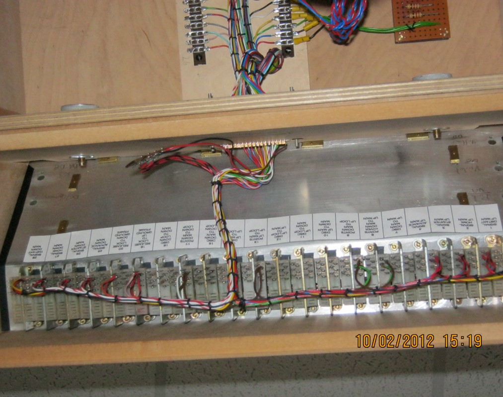
- Note! Railway signalling installations identify where the wire end goes to, not numbering the actual wire. There can be many thousands of wires in a modest sized relay room
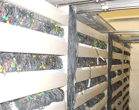
- Rear of relays in a small relay room. (No its not my layout, it belongs to Network Rail)
- All of the wire is black in colour
- Relays have 4 columns of 8 contacts
- Numbering A1 to A8, B1 to B8 etc..
- There are 4 contacts for the relay coils
- Each contact can have 2 wires in each
- Therefore
- (8 x 4) + (4 x 2) x 2 = 80
- YES 80 wires per relay
- There can be up to 20 relays or so per row and 8 rows
- You do the maths!!
- Wires are grouped by column then relay and exit troughing run through slots above relays
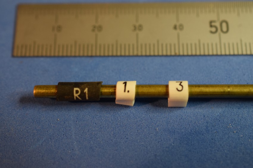
Cable Markers
Method 5: Wiring to the Baseboard 1
- Run wires in methodically, putting markers on as you go
- Run in DCC Bus supply
- Run in wires crossing the board to other boards
- Run in Traction tag to tag
- Run in section feeds to DCC Bus
- Run in switched wired to items on the board you’re working on
- Markers could be as simple as a sticky label printed with number upon them and then cut into numbered strips
Method 5: Wiring to the Baseboard 2
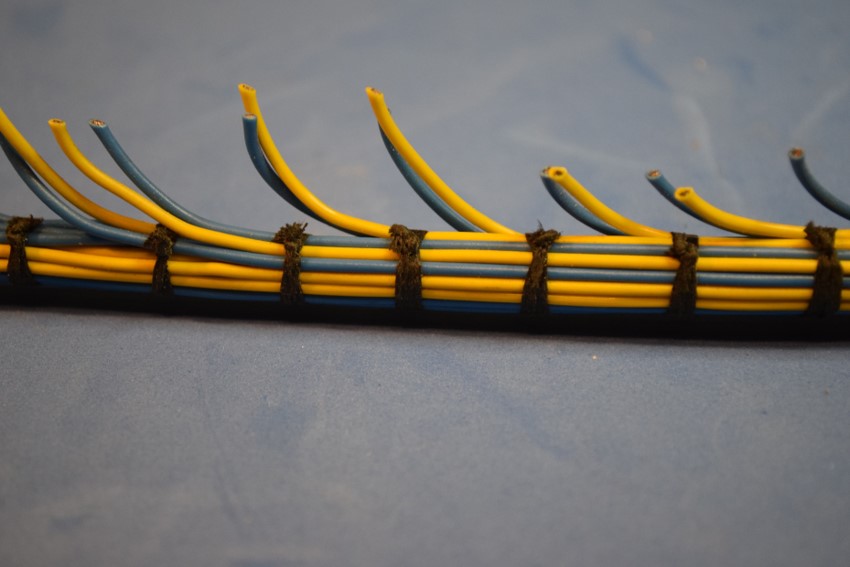
- Working from the centre of the board, straighten out to form a neat looking bunch. It’s never going to be perfect.
- Use off-cuts of wire, string or ty-wraps to secure the bunch
- If you have plenty of tie wraps, then as you work your way along, you can slide a reasonably tight tie wrap along, thereby keeping things neat. When you come to a wire leaving or joining the bunch, tighten that tie and use another in a similar manner.
- In a group team, there is usually someone who is incredibly neat and tidy, get him to do this job. It can be very therapeutic after wrestling with the compensation on his 9F
Method 6: Wiring to the Baseboard 3

Method 7: Peg- Board
- Piece of peg-board similar in size to your baseboard
- Paint it white on both sides
- Mark where cross members, track, point and signal modules go
- Mark where baseboard to baseboard connections and control systems go
- Run in your wires, using the holes in the peg board to hold them in position, not forgetting to put the relevant marker on
- Start to tidy up, from the middle, working outwards.
- Only lace up three or more wires of the off-shoots, can tie two’s together every so often
- Remove the loom from the peg board and thread through the holes in the cross-members
Method 8: Testing
- These steps are for both types of wiring method
- Lacing up before you solder to the terminals allows you to untangle the wires
- Once all wires run in, test continuity to ensure your wires go where you want them to.
- Start to solder wire end to the correct tag / terminal
- When complete repeat continuity and isolation testing
- Connect a 9V battery to the traction bus’s and check your polarities
- Count number of wires going to each terminal, hopefully they’ll match
- Do not forget to mark up your sheet when each stage is complete
- Photo shows rear of Dewsbury’s control panel.
- This controls the points and signals and is layout as a lever frame would be.
- With this type of switch, there is the ability to provide some rudimentary interlocking
- I.E Cannot have Distant Signal OFF without Stop Signals OFF as well
- Cannot have Signal OFF with points against it
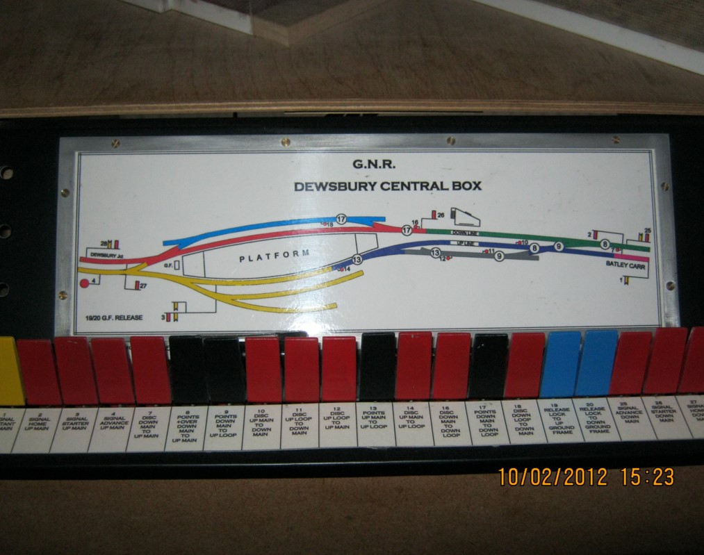
- Unused levers are not included on switch panel
- Switch levers are free to move but the rudimentary interlocking will prevent the operation of the equipment
- Yellow Levers are Distant Signals
- Red Levers are Stop Signals, including Ground Signals
- Black levers operate the points
- Blue Levers are the Release to the platform Ground Frame
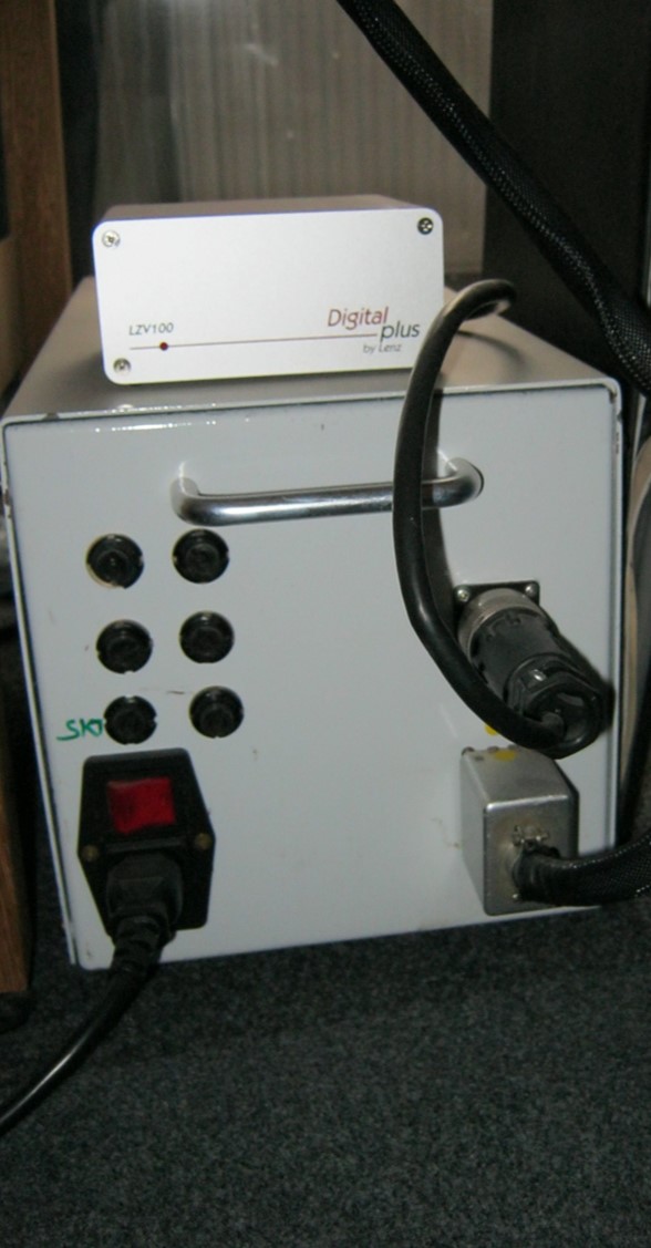
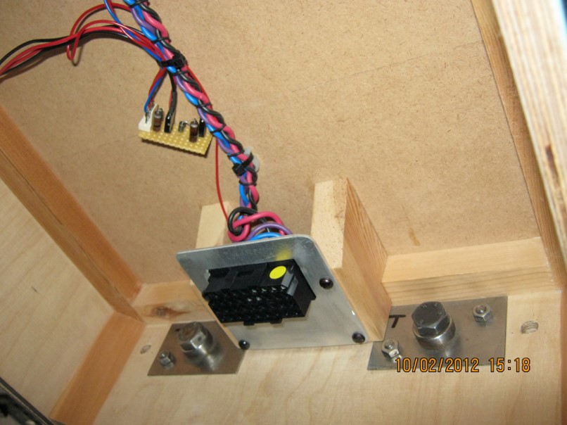
- Power Supply for Dewsbury is encased in a steel box
- All transformers are screwed down and fused on the primary side
- The mains lead is a standard IEC type lead
- A double 13 Amp socket is fitted at the other end
- The upper connector on the right goes to the Lenz DCC Command Station
- The lower right connector takes the low voltage supplies, the DCC Xpress-Net and the DCC Traction supply to the baseboard
- No mains voltages are available on the baseboards
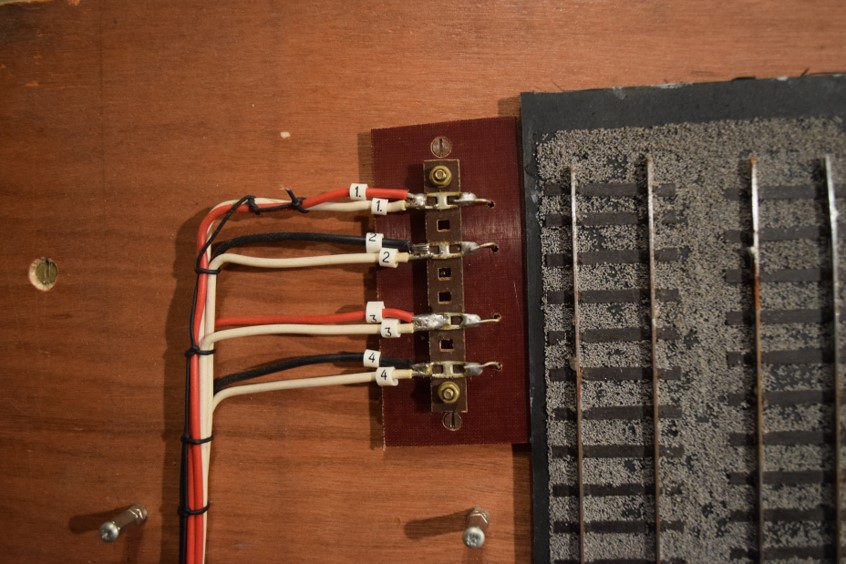
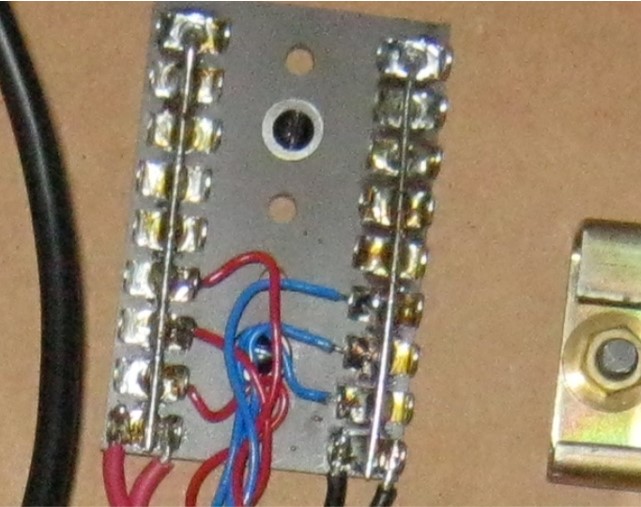
My Wiring Demo Board 1
- 3ft by 1ft board with two parallel lines cut into two section each
- Droppers soldered to outer web of the rails
- Dropper wire goes through the board and pops up by its tag
- Normally, these tags would be underside of the baseboard
- Tags 1 to 4: RS Barrier Strip; Cut into 10 contacts with 1,3,5,6,8 and 10 removed, 1 & 10 used for mounting
- Tags 5 to 12: Solder Eyelet; two soldered together, although singles would suffice
- Tags 13 to 16: Star Tag
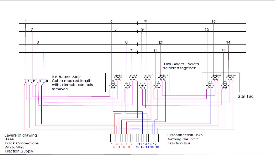
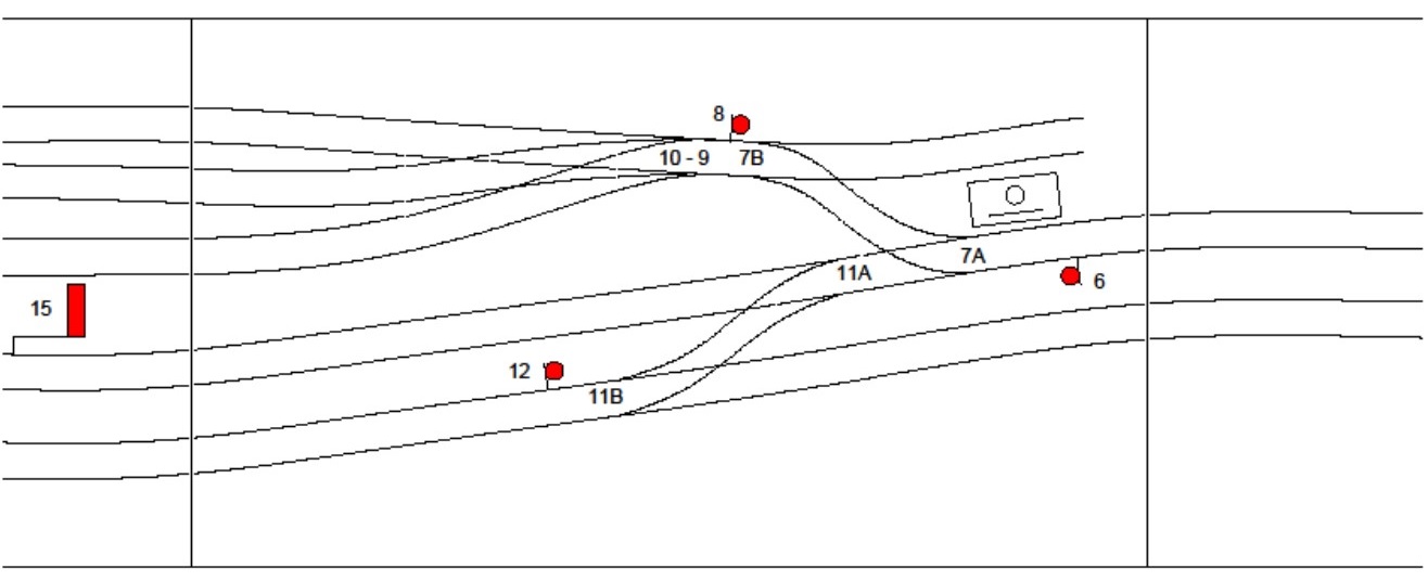
My Wiring Demo Board 2
- White wires connects tags of the same rail section (Shown magenta on diagram)
- Red Wires connect tag to DCC Bus (J)
- Black wires connect tag to DCC Bus (K) (Shown in blue on diagram)
- Lacing cord tied with a clove-hitch in the middle, leaving sufficient to reach the end of the board including wrapping round the loom in half-hitches every 20mm or so
- Loom secured to baseboard by self adhesive Cable Tie Mount
- I’ve used industry type disconnection links, enables a rail section to be isolated
My Wiring Demo Board 3