Skip to content
Virtual Scalefour North International
Menu
  • SCALEFOUR SOCIETY
  • JOIN TODAY
  • SCALEFOUR STORES
  • SCALEFOUR FORUM
  • CONTACT US
Menu

Watermouth – The Layout

Due to it’s length, this article by Stephen Howe has been split in to four parts:

  • Part 1 – The Layout (this page).
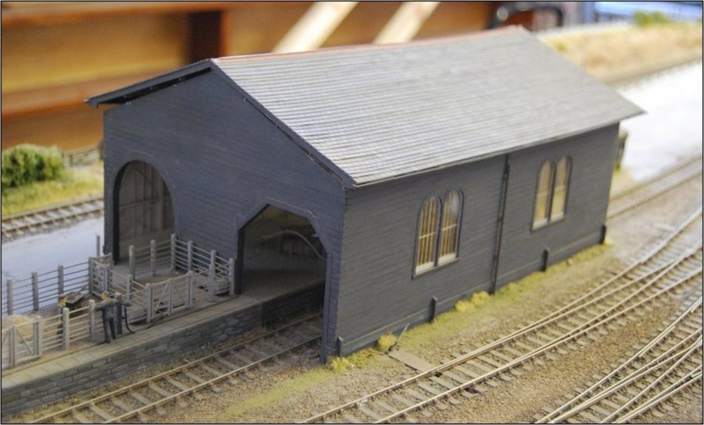
  • Part 2 – The Station Building (here).
  • Part 3 – Locomotives (here).
  • Part 4 – Rolling Stock (here).

A PDF version (19MB) of the full article can be viewed here.

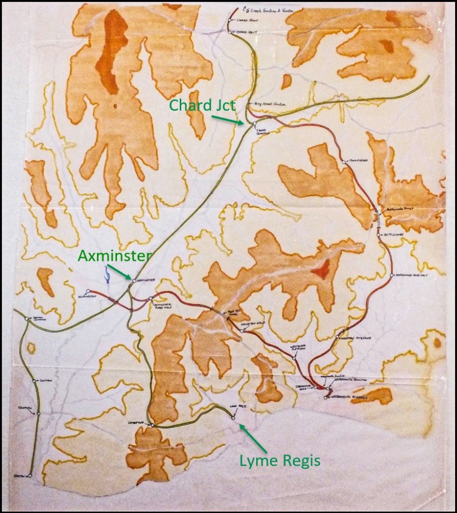
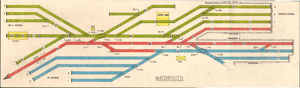
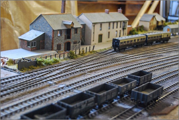
Watermouth represents a medium sized terminus of an imaginary GWR branch running south from Chard to the coast near Charmouth. Just short of the terminus on the north bank of the estuary, the branch is joined at St David’s Junction by a GWR/SR joint line running down from Axminster with another branch serving the village of Kilmington. The line crosses the tidal estuary by an iron viaduct and enters Watermouth Riverside which is also assumed to have a branch running on to Watermouth Docks. The station arrangement draws inspiration from Kingsbridge, Weymouth and Kingswear. Watermouth Docks are assumed to be an embarkation port for steamers to the Continent and the track plan is designed to accommodate busy summer passenger traffic, including a daily Sleeper to London and through trains from the Midlands, London, Taunton and Exeter, as well as local branchline services.

In the Master Plan, this station lies on the bank of an estuary and a single line section on a long bridge over the river (based on the Taw bridge at Barnstaple) links it with St David’s Junction. Because this bridge has a weight restriction, ‘large’ engines come off their trains at the Junction and go to a small MPD, whilst the train is taken on to the main terminus by a lighter locomotive. The corresponding empty stock and light engine workings should allow for a variety of interesting traffic movements.

The layout was begun over 45 years ago by the late Pat English, a long-standing member of the Falmouth Model Railway Club and represents a pioneering example of early P4 modelling. Pat was a meticulous modeller and researcher and the layout was designed to strict prototype practice.

Originally conceived as a ‘U’ shape with stations on either side of the room, it was later rebuilt following a house move into a ‘L’ shape and the bridge over the estuary and the junction station were abandoned, (This station was given to another Club member who has also since passed away and in memory of him it was re-named ‘St. David’s Jct.) Although never developed to a fully scenic finish, enough has survived to make a full restoration feasible, particularly since ‘St David’s Junction’ has also since come into Club custody.

The location map which follows was found in a box of oddments when the layout was dismantled, and gives a clear indication of the geographical location of the Branch, and its relationship to the railways of the area, both real and imagined.

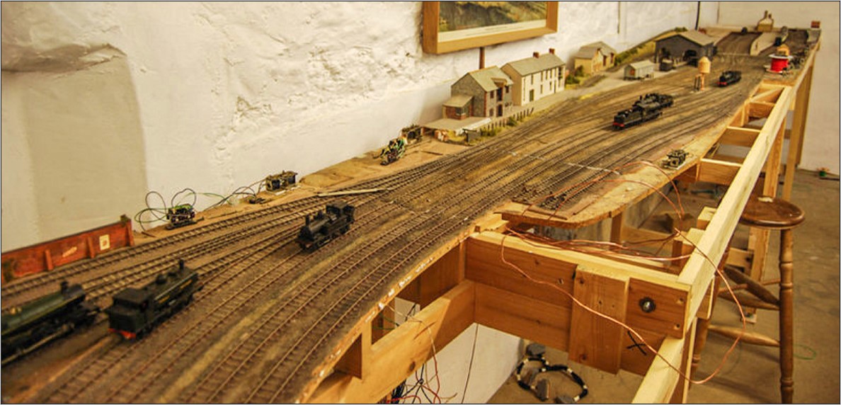
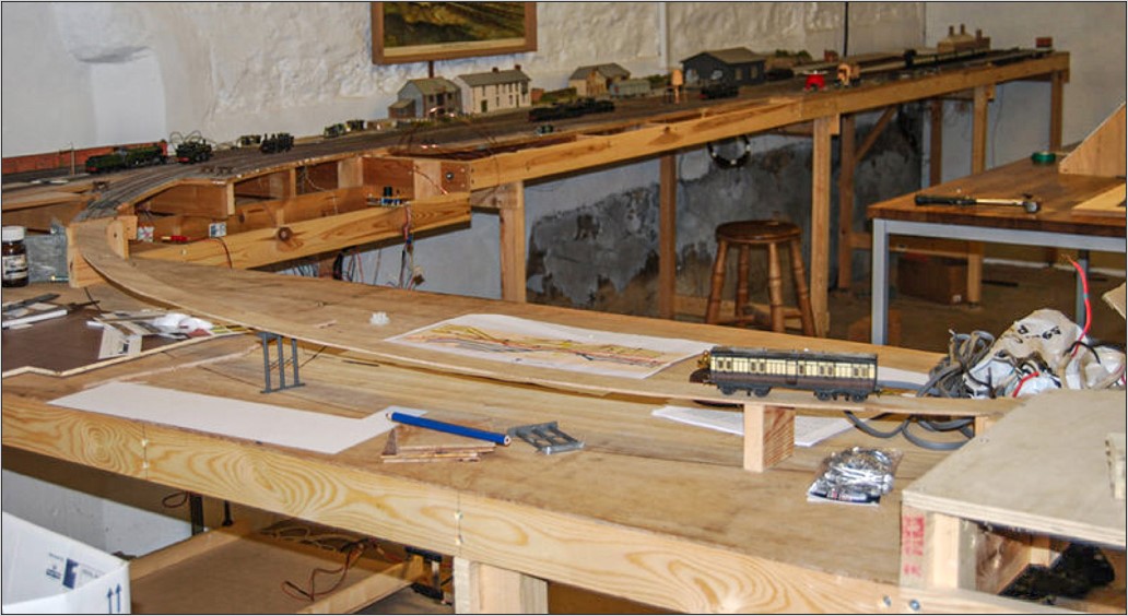
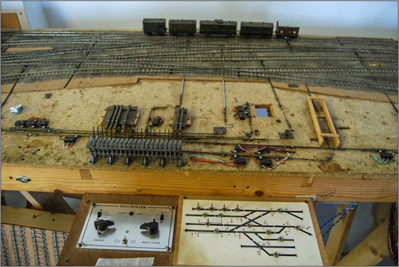
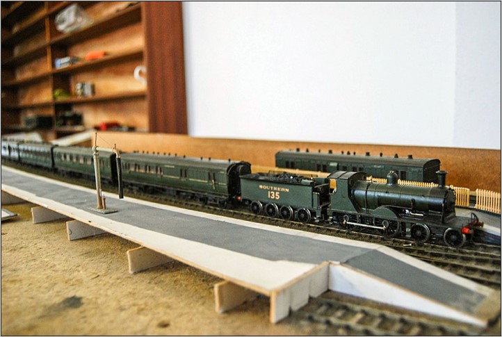
As will be seen from the photos, the model, even in its present form, is impressive. We hope this presentation will encourage other Cornish finescale modellers or even those further afield, to join in the project. The layout has been relocated to the Helston & Falmouth MRC’s clubroom at Gunwalloe near Helston, where the detailed work of revising the outdated wiring and point control is well in hand. The layout has been completely rewired, a new control panel constructed to enable full cab control with Pictroller controllers, and Cobalt point motors installed.

For details of meetings and working sessions please contact Steve Howe at the address below: cornwall@scalefour.org or go to www.hfmrc.com

We hope this presentation will bring the project to a wider audience and hope we may encourage increased interest in bringing this historic layout back to life.

Schematic Diagram of Watermouth Terminus
Watermouth set up for the first time, still on the original baseboard framing, chipboard baseboards and H & M point motors from the late 1970’s!

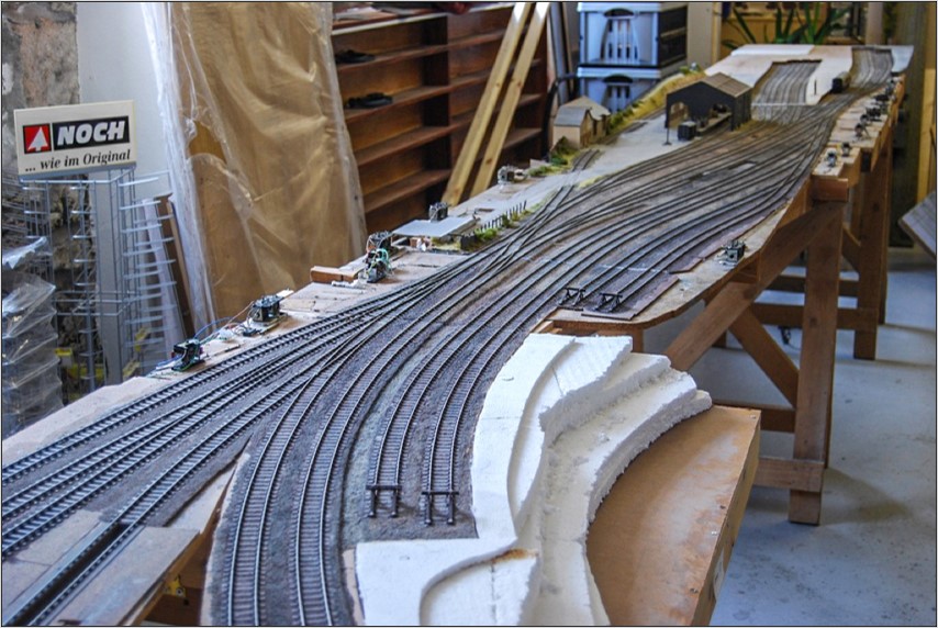
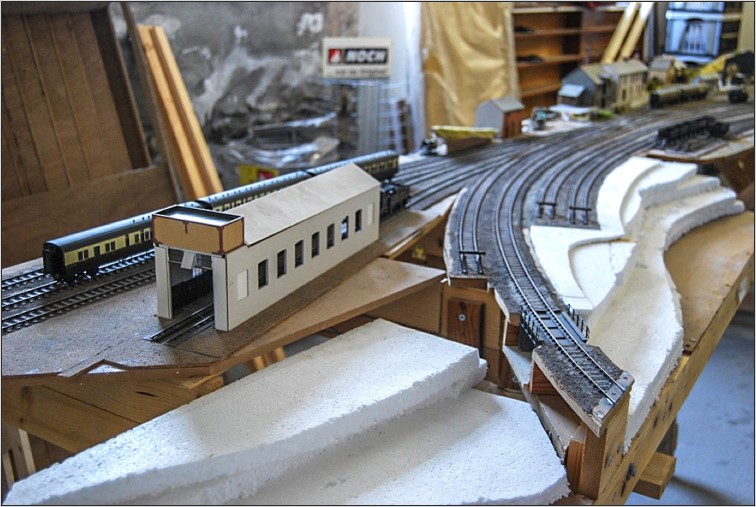
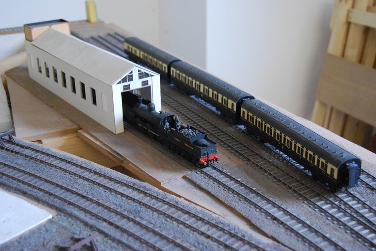
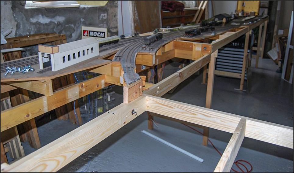
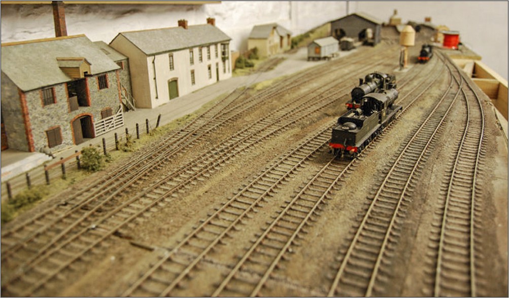
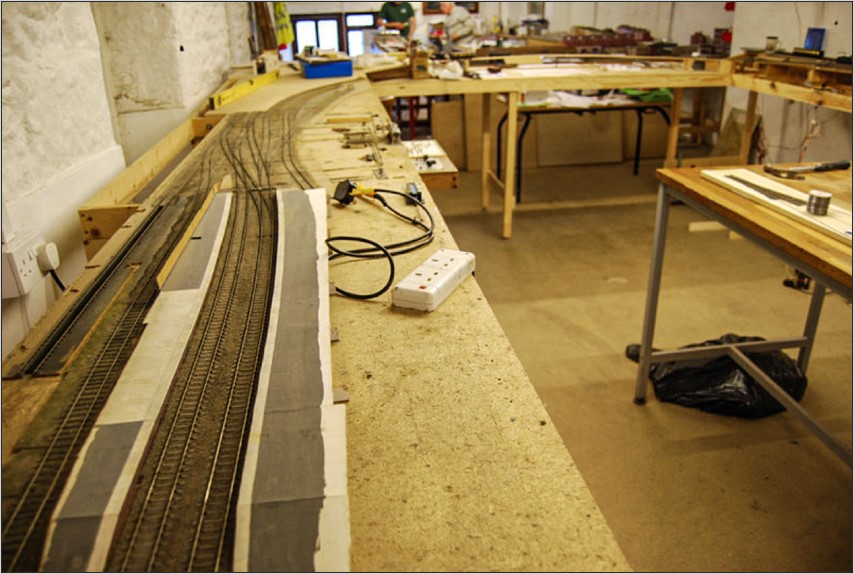
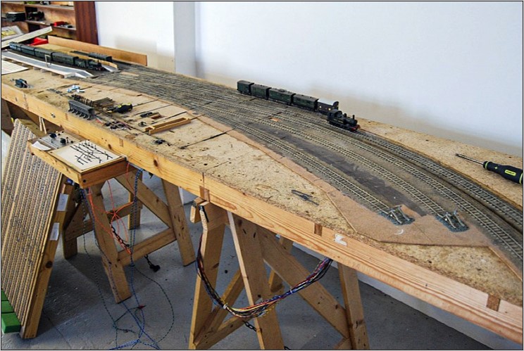
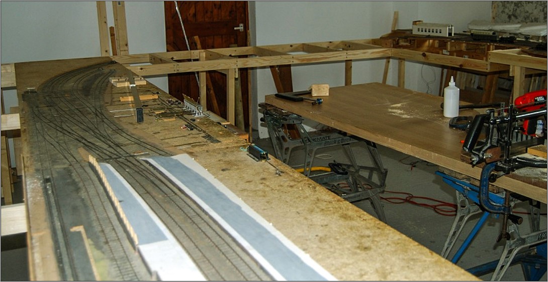
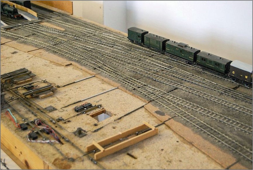
The baseboards were originally constructed on half inch chipboard and 2″x1″ timber as was the custom of the time; track is fully chaired ‘Brook-Smith’ pattern with correct 2 bolt chairs and captures beautifully the ‘flow’ of the prototype. All this has withstood the years remarkably well, but as the baseboards were altered and rebuilt at various times, the depth of the baseboard members varied from board to board making setting up and dismantling unnecessarily awkward (the layout was never intended for exhibition viewing) The main baseboard framing has been replaced with new timber of consistent depth, new alignment and fixing bolts installed and new supporting frames built.

The baseboards representing the estuary and bridge connecting the two stations have been reconstructed and the entire layout measuring some 24′ by 18′ has been fully erected for the first time in many years in our Clubroom. A suitable cassette and stock storage system will be created to replace the original and highly complex fiddle yard that Pat constructed and which has since found a new home with a member of the Scalefour Society.

Watermouth baseboards now re-mounted on new frames. The ‘flow’ of the trackwork is one of the great visual assets of this layout.
The Watermouth station throat. The single line in the foreground is the approach from the long curved bridge crossing the estuary. The locomotive shed is for engines using the station on a regular basis, the servicing point across the river at the Junction is for locomotives too heavy to cross the bridge, or Southern engines whose trains terminate there.
Carriage sidings adjacent to the loco shed. The coaches are Slaters Toplights, the Dean Goods is the Finney kit.
The dropped frames for the estuary boards. The ruling radius for the proposed iron bridge is around 5’ 6”. Heavy checkrailing will be the order of the day!
Watermouth station occupies most of one side of the layout. The foundation for the curved iron bridge is in place in the foreground. Much remains to be done on these sections which had to be rebuilt on a wider radius curve when the layout came into the club’s custodianship.
A view over the Up sidings, the warehouses are constructed from card and watercolour following ‘Pendon’ techniques. Pat English was extensively involved with Pendon as Wagon Steward, during his retirement and his modelling reflects the standards achieved there.
Pat was a great wit, and examples often turned up in his work. The corn merchant’s premises we believe are based on a real prototype, if anyone recognises it we would love to know!
A view towards the terminus, the sidings on the right are linked to the docks branch suggesting they were intended for exchange traffic to and from the Docks
The station building at Watermouth with the later Buffet building beyond. Constructed of plastikard and pasteboard, it again will have been based on a prototype, the nearest we can find so far is part of the complex at Oxford before it was ‘rationalised’. The station buildings are looked at in more detail later in the article
The Watermouth goods shed based on the classic Brunelian design. Constructed entirely in Plasticard with full interior detail.
Curiously a water tank and inspection pit were placed on the run-round road. Given that there is already a locomotive shed in the complex, it seems a bit of overkill, unless anyone can advise differently?
The terminus boards from an unusual angle during re-wiring works. It does however give an indication of the long sweeping curves which characterise this layout. The Docks Branch is top left leading onto a section of baseboard that has since been lost.

St. David’s Junction

Early view of the junction in very embryonic form. New frames were made to be consistent with the rest, and the opportunity taken to extend the rear of the baseboard by 6” to create standard 4’ x 2’ units. There will be a great deal of work needed to bring this section forward because despite being over 40 years old, it still requires chairs to much of the track, and the trackwork itself is still in basic ‘ply and rivet’ condition.
An early view of the junction boards before they were widened at the rear. The far left-hand corner will be occupied by a small MPD and turntable, The estuary and bridge section is in the distance linking the two stations together.
St. David’s Junction has some interesting and slightly esoteric trackwork, which we are still trying to work out! According to the diagram three lines converge into one with what is we think, a locomotive stabling road along the rear. Any observations gratefully received!
All the pointwork on this section was manually controlled from a GEM lever frame. Over the years much of this has failed, and the long term plan is to replace all with Cobalt motors.
The conceit for St David’s Junction is that it is the meeting point for joint GWR & SR routes vying for the lucrative trade arising from Watermouth Docks. We are still unsure as to whether Pat intended Southern trains to have running rights into Watermouth, or if these services terminated at the junction. One thing is for sure and that is the iron bridge would have a weight restriction requiring heavier locomotives from long-distance trains to be detached and replaced by ones of lighter axle loading. A stabling depot and turntable being provided at the Junction for their use.

Click here for part 2 of this article which covers the station buildings.

Around the Show

  • Welcome
  • Historical Interest
  • Layouts
  • Demonstrations
  • Showcase
  • Traders
  • Cinema Coach
  • Scalefour North Retrospectives
  • Society Information
  • Miscellany
  • Visiting Societies
  • Show Index
  • Credits

Site Search

About

Virtual Scalefour North International 2021 is an online finescale model railway exhibition, organised by the Scalefour Society.

Privacy

Privacy Policy

©2023 Virtual Scalefour North International | WordPress Theme by Superbthemes.com