Introduction
Kits or ready-to-run conversions are a useful basis to build our model locomotives for P4. However, the level and quality of detail provided by the manufacturer can vary and, in many cases, there’s scope to add extra detail or replace parts with better representations of the real thing.
This presentation covers my approach to some of these extras. It uses examples of some of my more recent locos to illustrate typical details I like to see on a model. It reflects my preferences and in no way precludes other ideas or approaches to loco construction and detailing. As my modelling interest in ex-LMS and BR Standard locos, the examples are based on these types but I’m sure the basic principles are equally applicable to many other prototypes.
I like to view my models from a fairly side on perspective so the side-on profile is important and I don’t want to see gaps where they shouldn’t be so as to capture the solidly planted character of real locomotives. In general, I’ve found the kits I’ve built to be most lacking in the area below the footplate – other than cylinders and valve gear – so that is the area I’m going to concentrate on here. I have to say, the details illustrated are generally representations of the parts in question rather than exact scale details but, to my mind, they serve the purpose.
The detail and replacement parts have generally been made using basic hand tools such as fine saws, drills in hand held pin chucks, files and broaches. Materials are mainly brass or nickel silver in the form of sheet, strip, wire, tube and sections. Use is also made of spare etch fret material and spare etched parts left over from previous models or provided as alternative parts. Recently, I have commissioned some custom etched parts.
I hope you will enjoy my presentation and find it helpful or even inspiring. Some of the information and photographs presented have appeared in my posts on the S4 Society Forum web site, so if you’ve already seen some of them, please bear with me. Most of the photos used were taken by me but those of the completed locos are by David Clarke and the under construction shots of the Caprotti fitted BR Standard 5 were taken by Barry Norman. I hope they won’t mind me using them for this purpose.
Scope
As stated in the Introduction, I’m going to mainly feature the area below the footplate, specifically:
- Bogies and pony trucks
- Brake rigging and sand pipes
- Injectors and pipework below the foot plate
- Aspects of valve gear.
To help illustrate my approach, I’ve chosen selected details from the following completed locos:
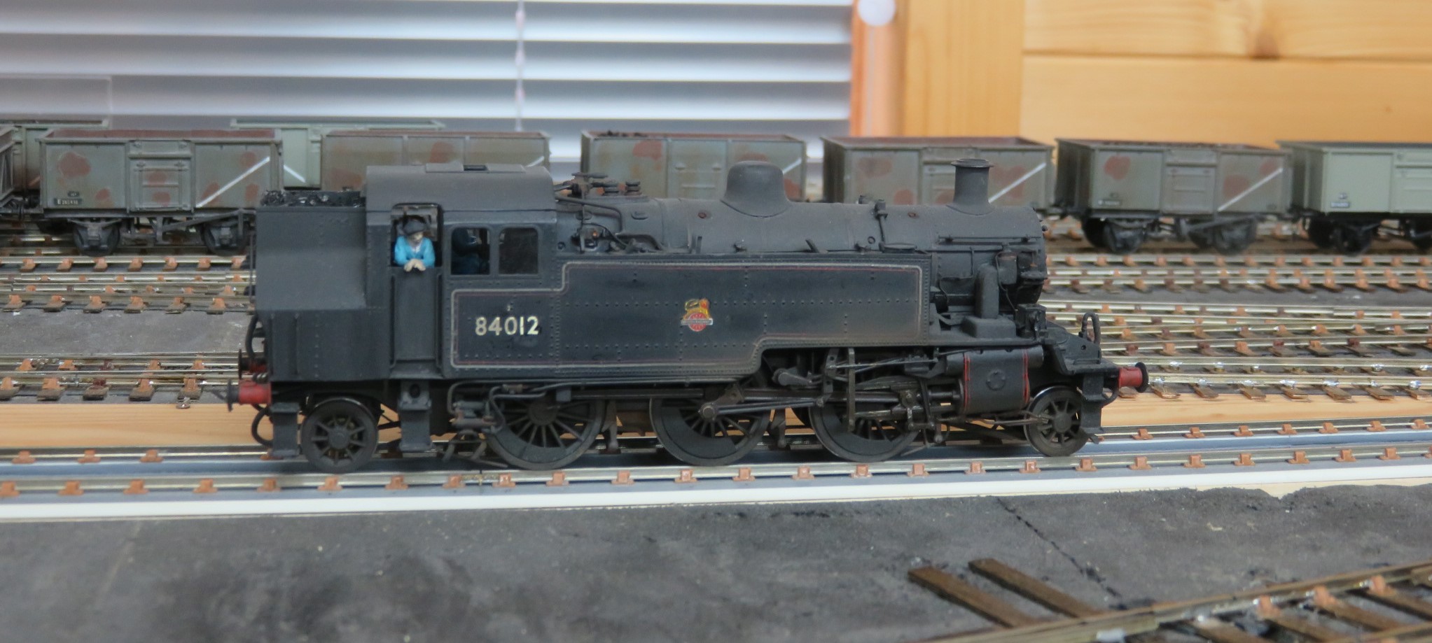
BR Standard Class 2, 2-6-2 tank
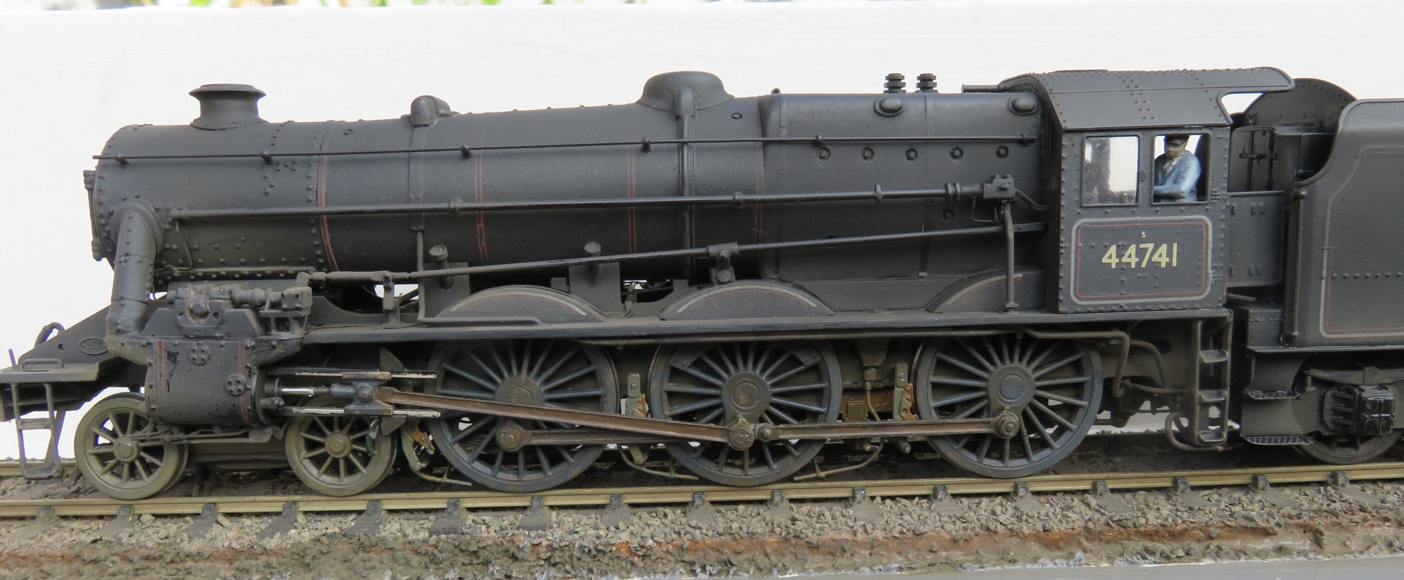
ex-LMS Stanier Black 5 with inside Caprotti valve gear
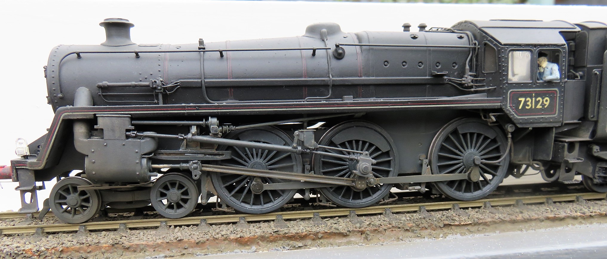
BR Standard Class 5 with Caprotti valve gear
And partially completed locos
ex-LMS Stanier Black 5
ex-LMS Ivatt Class 2, 2-6-2 tank
ex-LMS Rebuilt Royal Scot.
Sources of Information
Before we look at specific details, a brief thought about sources of information. In trying to improve a kit, obviously any additional or replacement parts need to look something like the prototype part. Typically, sources used have included photos, GA and Pipe & Rod drawings and dimensional surveys of surviving locos in preservation. This last has to be tempered with some caution because some parts of preserved locos are not the same as those fitted during service; one of the worst aspects of this is injectors where, say, exhaust steam injectors are replaced with a second live steam unit or are not piped up properly and live steam injector substituted by one of a different design or configuration – Bulleid pacifics are particularly prone to this latter problem.
In the past, I’ve purchased drawings from the Oxford publishing catalogue and, more recently, from the NRM (I found that a bit of an uphill struggle and rather expensive). I’m also lucky in my area of interest that we have the excellent Wild Swan profile series of books which contain many detailed photos and reproductions of a selection of drawings. Otherwise, there are published photos in books and magazines (although, sadly, the sort of detail we’re interested in here is often lost in deep shadow) and possibly from like minded fellow modellers – one of the benefits from posting on the internet.
Bogies and Pony Trucks
I can’t imagine a kit which doesn’t include the requisite bogie and/or pony truck(s) but my experience, to date, is that they rarely provide any representation of the load transfer arrangements found on the prototype. Considering the loads involved – typically 15 to 20 tons for a bogie and 10 to 15 tons for a pony truck, these transfer arrangements are necessarily massive and strong whilst still allowing rotation and/or sliding relative to the fixed frames. The two types of weight transfer arrangement are a central pivot/bearing block at the bogie centre or over the pony truck axle or side bearer pads located roughly under the side frames of the chassis. There most certainly isn’t any daylight between bogie or truck centre and the loco frames often seen on models.
Such arrangements normally mean the bogie and truck frames do not move up or down relative to the main frames so any suspension movement has to be accommodated by the bogie or truck axles. This is an added complication compared with free floating bogies and trucks often found on models.
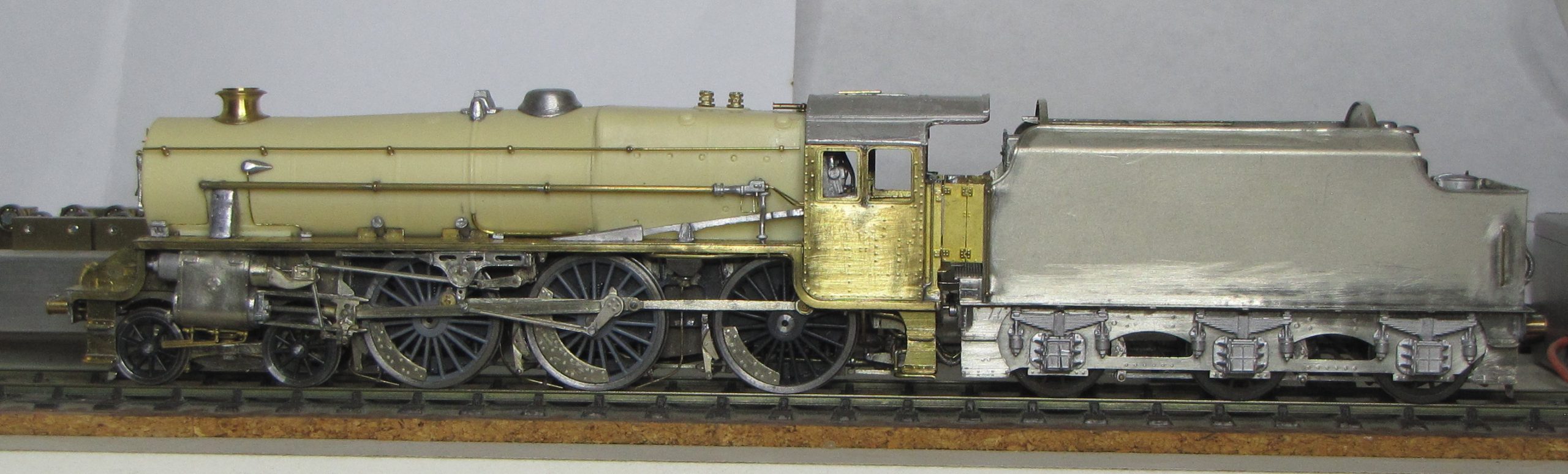
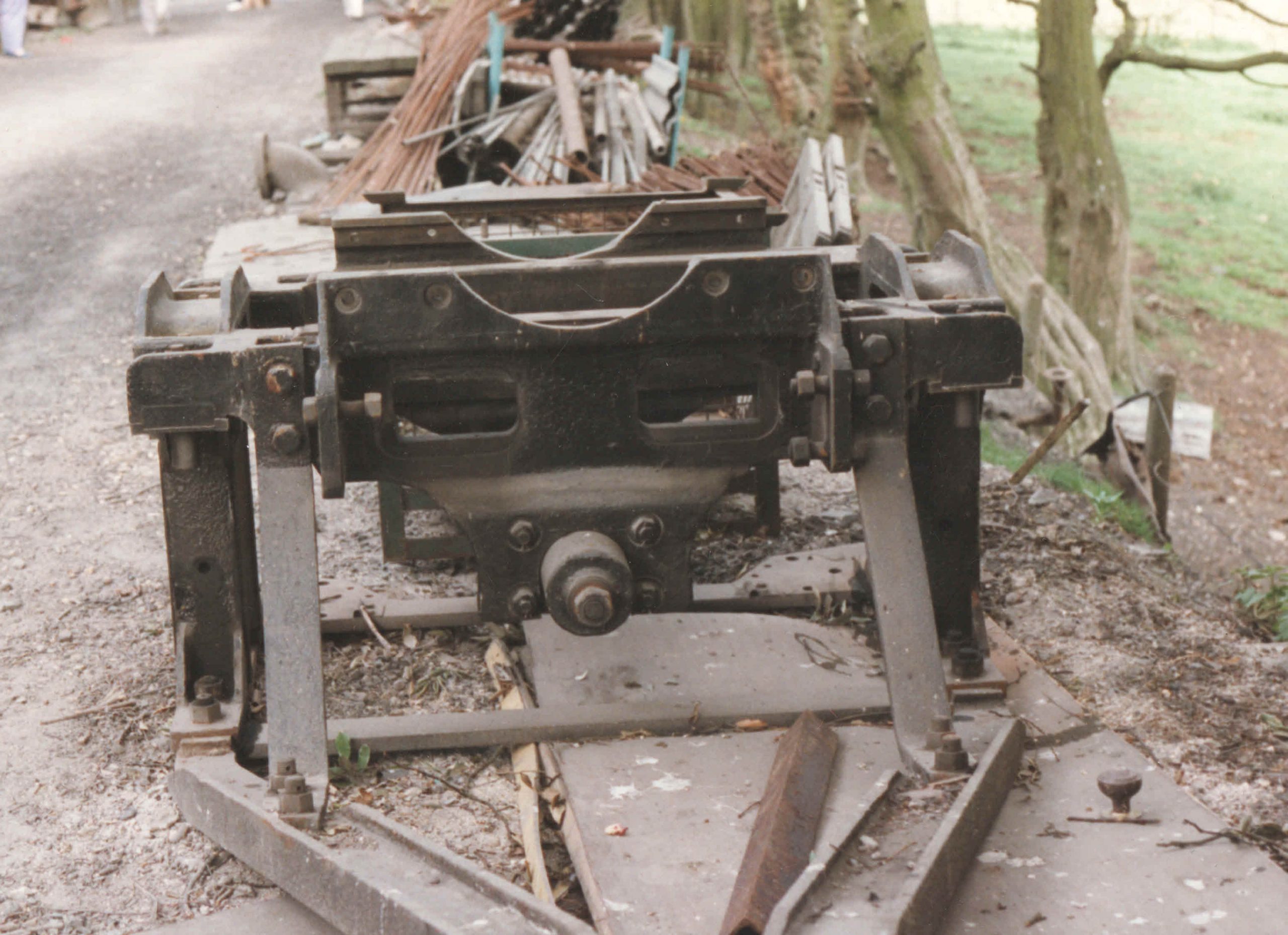
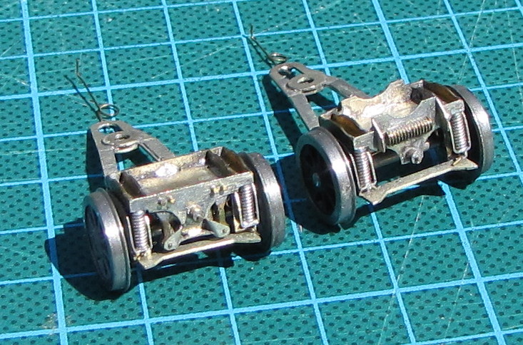
Here’s a typical ex-LMS bogie from the Stanier era (BR used the same design on Standards), showing the side bearer pads upon which two ball and cup pads, fixed to the bottom of the main frames, rested.
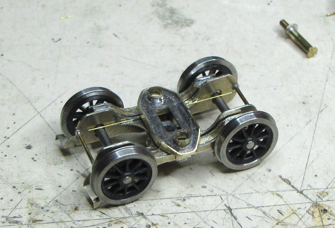
Here’s my attempt to replicate at least the externally visible features of this type of bogie, in this case, a modified Brassmasters item. I’ve applied similar arrangement to Comet bogies. Clearly not an exact replica as my version doesn’t dip down in the middle. I consider that too difficult without special castings and in any case cannot be seen on the completed model. Also, the brass tube representing the bearing pads are fixed to the bogie and slide under the chassis bearing plate rather than the prototype arrangement. That’s to accommodate the Brassmasters side springs which transmit the load from the loco to the external compensating beams. On my Comet bogies, the fixed pads are on the loco frames, as they should be.
The light wire spring resting on top of the axles is not part of the loco suspension but merely serves to hold the bogie up in contact with the loco frames.
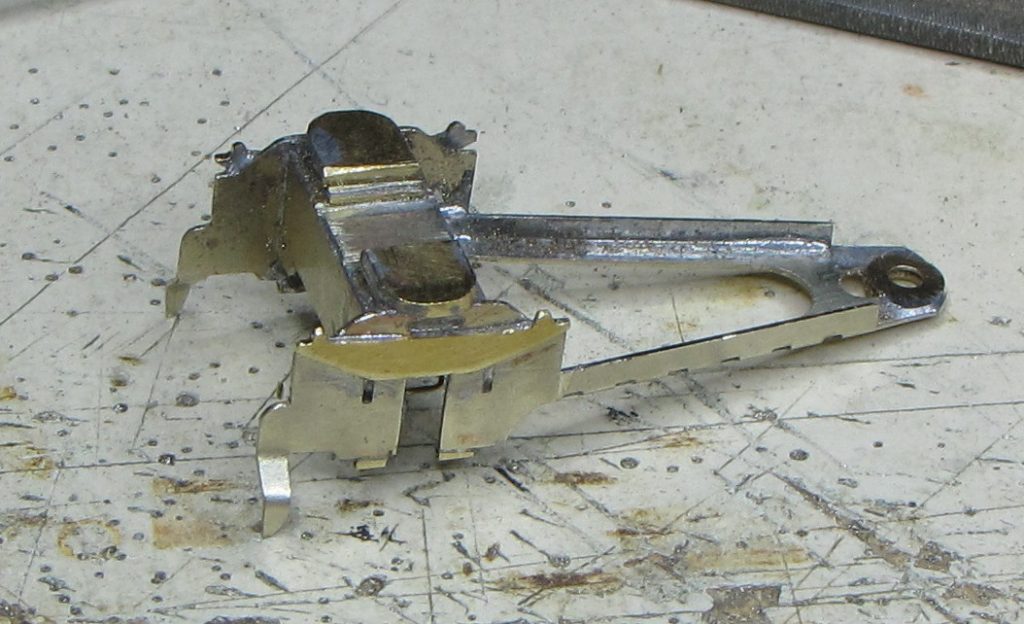
Next we have an ex-LMS plate frame pony truck. No prototype photo but the model shows the basic arrangement. Similar concept to the Stanier bogie but of course the side bearer pads have to be much closer together to fit between the wheels. This example is a modified Comet truck for use under a Stanier 8F (a friend’s model). The truck axle is sprung using diagonal hairpin springs inside the truck body.
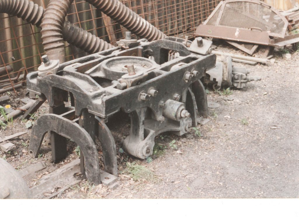
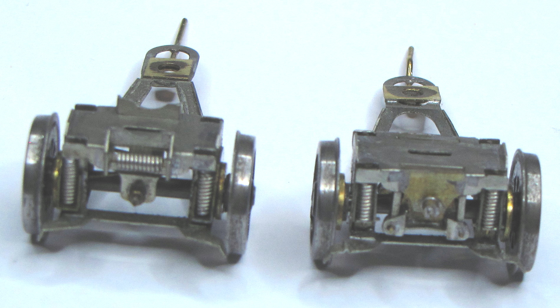
The type of pony truck fitted to Ivatt Class 2’s and 4’s, and also used on the equivalent BR Standards, was a bar framed type quite different to the previously standard LMS plate frame trucks. Much lighter in construction it used coil rather than leaf axlebox springs. There were two different side control versions – coil spring, used on 2-6-0’s and at one end of 2-6-2’s and a swing link version used at the other end of 2-6-2’s.
Here are the two different types seen at the Mid Hants Railway.
My version for the Ivatt 2-6-2 tank are modified by scratch made additions to the very basic Comet etched frame. The frame mounted pintle slides on the flat area on top of each truck. Side control is by means of the wire springs protruding behind the truck pivot, which engage with the loco frames. The axles are again sprung using diagonal hairpin springs mounted inside the truck body.
Since I made these, Brassmasters have produced a kit for the spring side control type which is a good representation but has been reduced in width to accommodate EM gauge models, so is slightly compromised in proportion. Nevertheless, I used them under the BR Standard 2-6-2, modifying one to represent the swing link type.
(S4 member Pete Tarver has produced an etch to convert the Brassmasters etch to the swing link type. See https://www.scalefour.org/forum/viewtopic.php?f=135&t=6252&p=73262#p73262
On sale from Rumney Models – X.15 Ivatt Pony Truck Detailing – £1.50)
Brake Rigging and Sand Pipes
Again, all the kits I’ve built have provided basic brake gear covering the hangers, brake blocks and stretchers and, sometimes, the pull rods. Here, it’s not so much adding detail as arranging for the assembled brake gear to be removable where the wheel sets are retained by a keeper plate and part of the system (usually under the cab) remains fixed to the chassis. I often make the split between fixed and removable sections at the rear stretcher or at the turnbuckle adjuster in the rear section of pull rod.
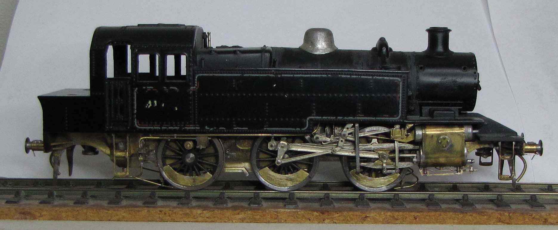
In the case of the Ivatt and BR Standard 2-6-2 tanks, the brake rigging is complicated by the brake cylinder and crank pass through the A-frame of the rear pony truck and the pull rod extends forward, below the truck pivot/mounting screw.
On the Ivatt tank, although the kit brake hangers are used, the rest of the brake rigging is home made as the kit incorrectly provides a central pull rod (correct for the BR Standard) but wrong for the Ivatt which had twin pull rods forward of the rear stretcher.

Older locos and those of GWR origin tended to have gravity sanding with relatively large pipes protruding down near the wheels. The locos I model all had steam powered sanding which had smaller sand pipes, typically 15/16″ O/D which, together with the mass of the sand ejector gun, required support near the discharge end of the pipe. This support often took the form of lengths of angle iron fixed to or close to the spring hangers with an outward facing bracket to steady the sand pipe and ejector. Originally, I made these brackets from narrow strip material, but eventually had some etched ones done, although they sometimes need trimming back to remove the vertical leg.
Of course, with these locos there should be a steam pipe leading to the sand ejectors. The steam pipes are typically only 5/8″ O/D (0.2 mm in 4 mm scale) and would be quite flimsy and prone to damage, so I leave them off.
On model with a keeper plate, I attach the sand pipes and their brackets to the keeper. On some locos this arrangement traps the brake rigging within the sand pipes and, although not fixed to each other, the keeper plate and brake rigging become a single item. On some others, despite the apparent entanglement, I found that I could wiggle the two sections together and apart, a bit like solving one of those brain teasers you get in Christmas crackers.
Ejectors, Injectors and Pipework
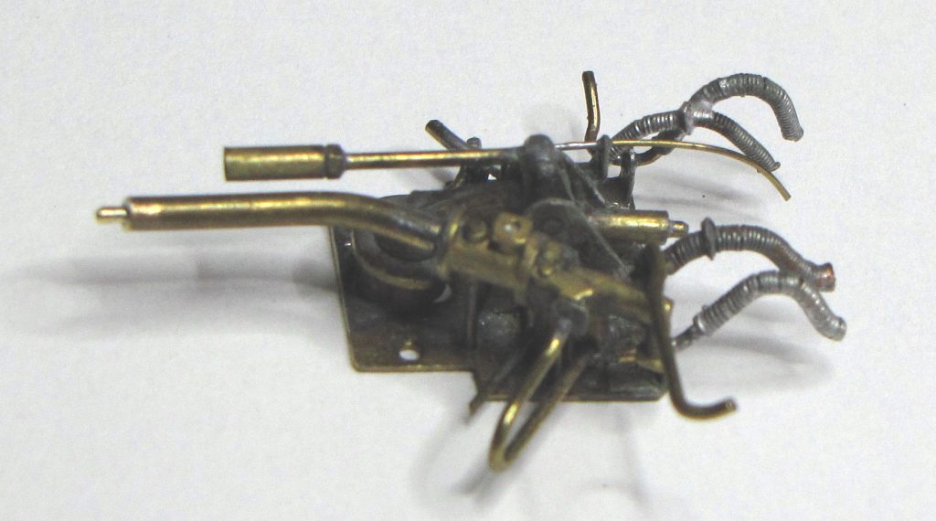
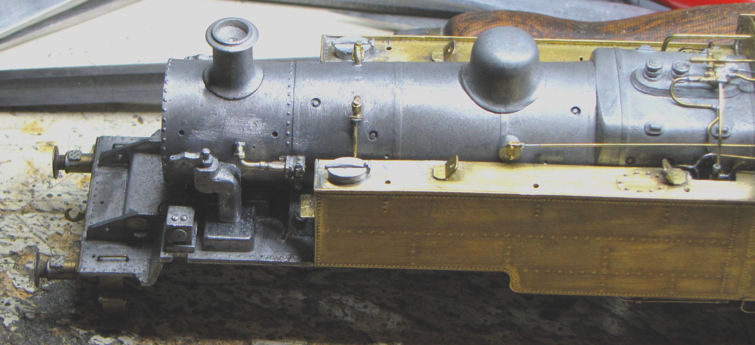
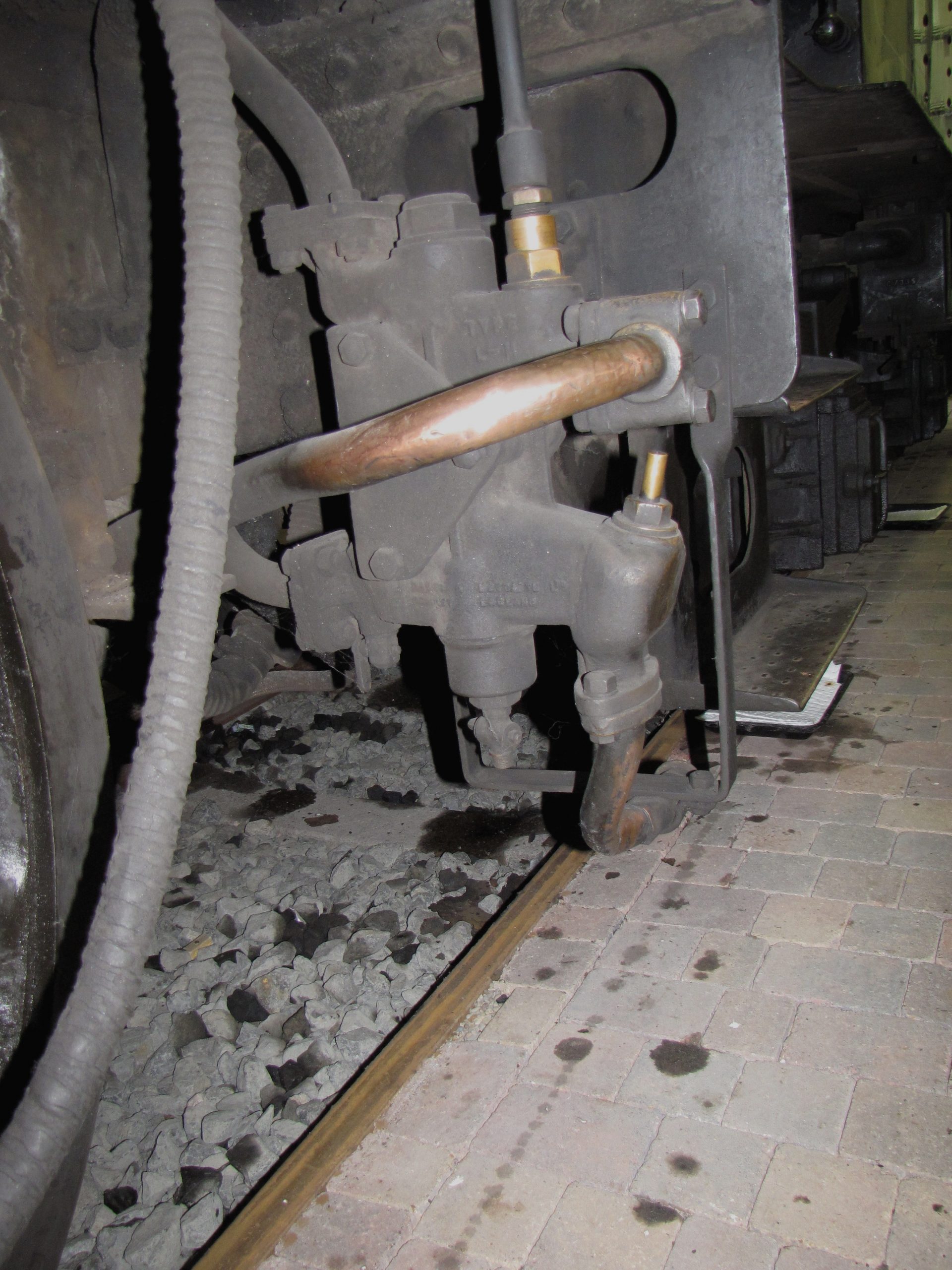
Ejectors are usually supplied as castings which can be enhanced by adding fine wire to represent the various drains with which these devices are fitted. However, I could not find a suitable casting to represent the ejector fitted to BR Standard locomotives, so items resembling the real thing have been made from wire, tube and parts sawn and filed from flat material.

Injectors are also usually supplied as castings and some are excellent and can be used as supplied. Again, sometimes the supplied castings aren’t good enough or are not the right type or configuration. In these cases, I have made replacement items from wire, tube, washers and bits of spare etch fret.
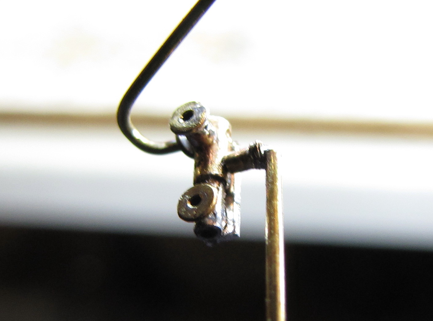

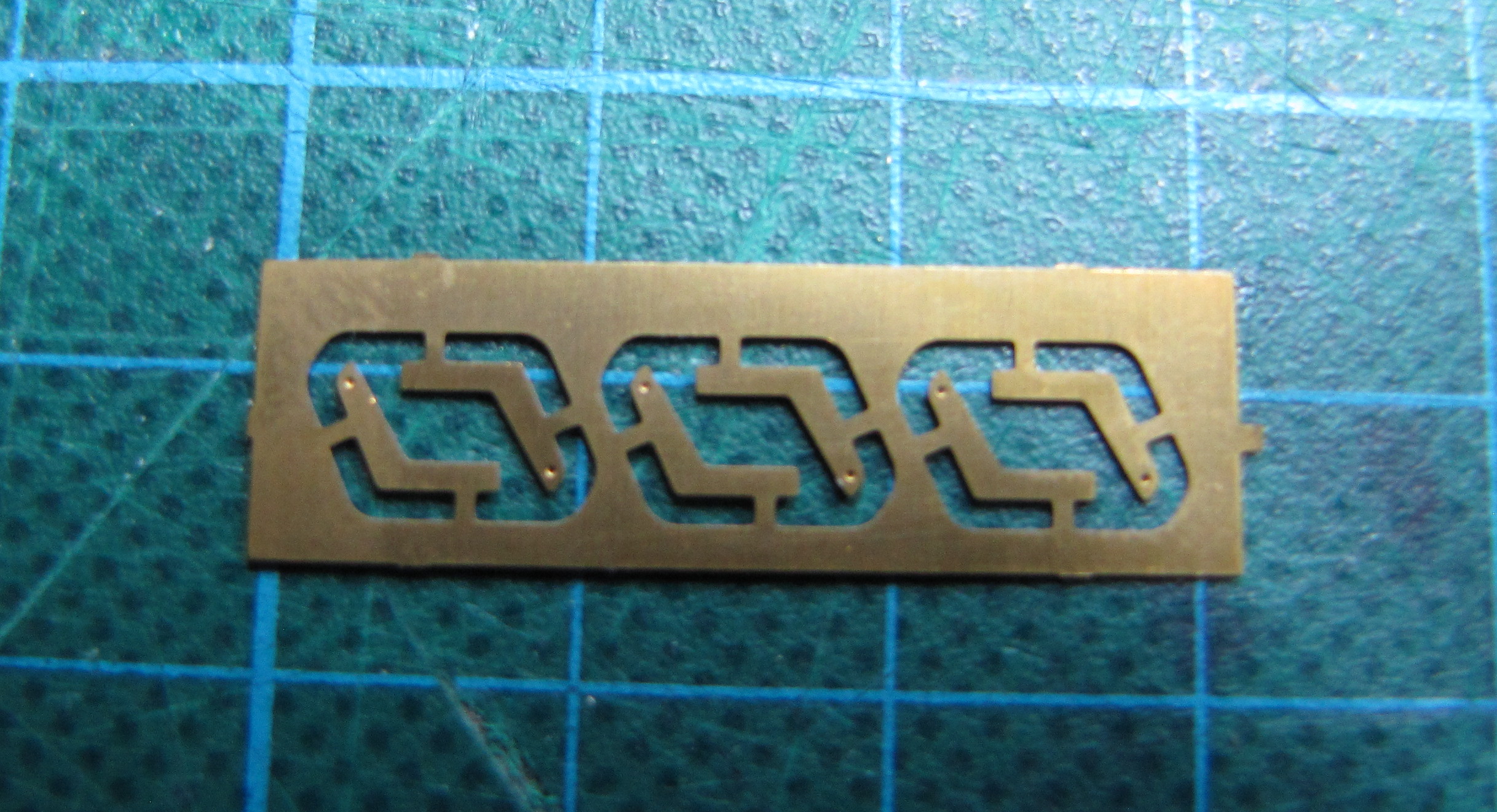
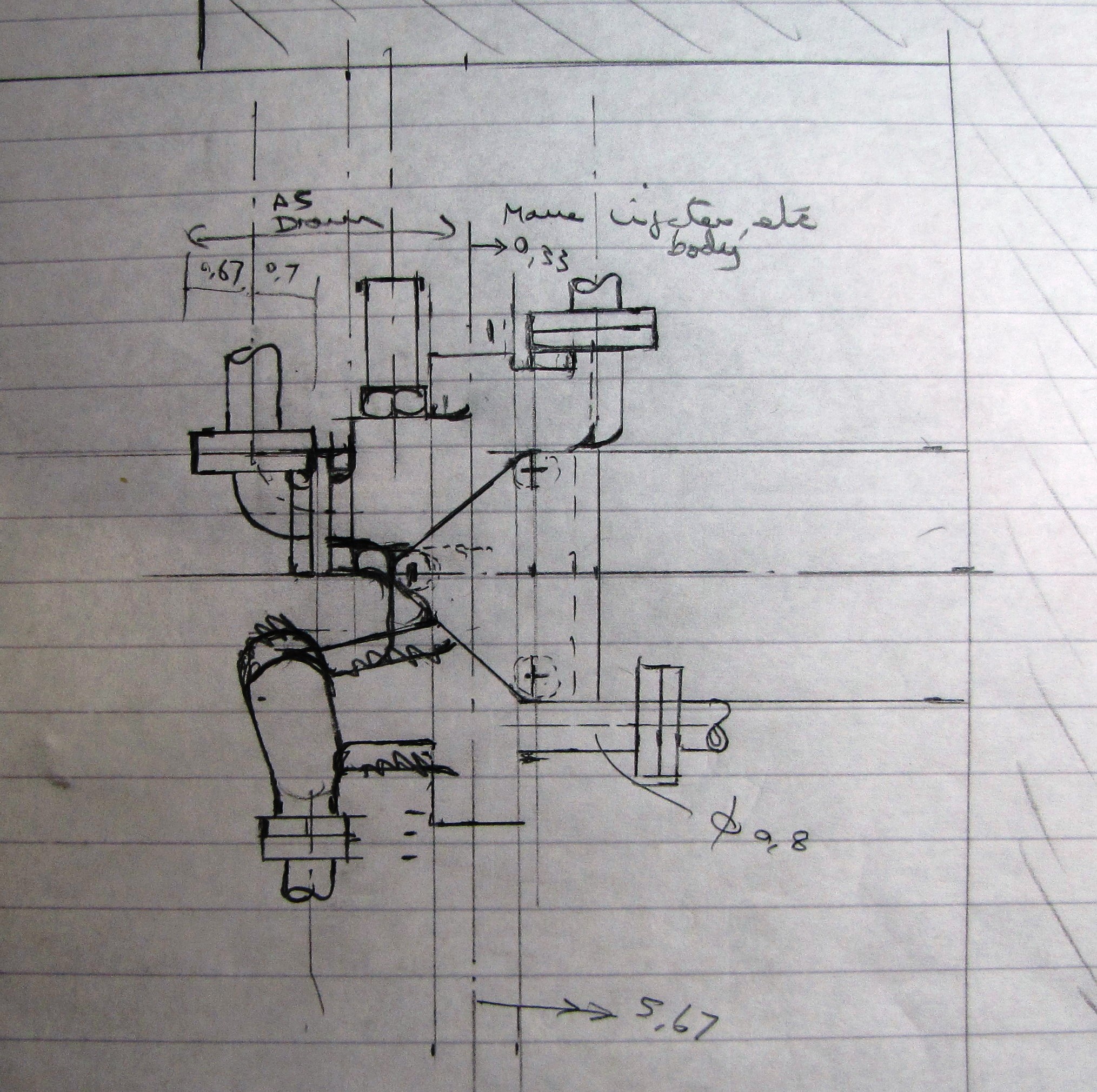
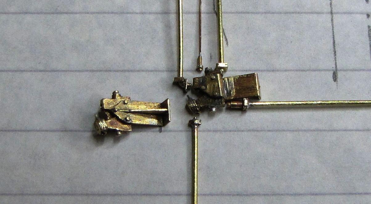
The injectors for the Ivatt tank were an altogether bigger challenge. These injector are a completely different shape to the normal type and, as far as I know, are not available commercially. Study of the injector body revealed that it is quite a flat shape with rounded edges. This made me think that it could be replicated by laminations of flat material so some custom etches were commissioned, covering the body, overflow, various flanges and the characteristic mounting bracket. They proved fiddly to say the least but I’m pleased with the results.

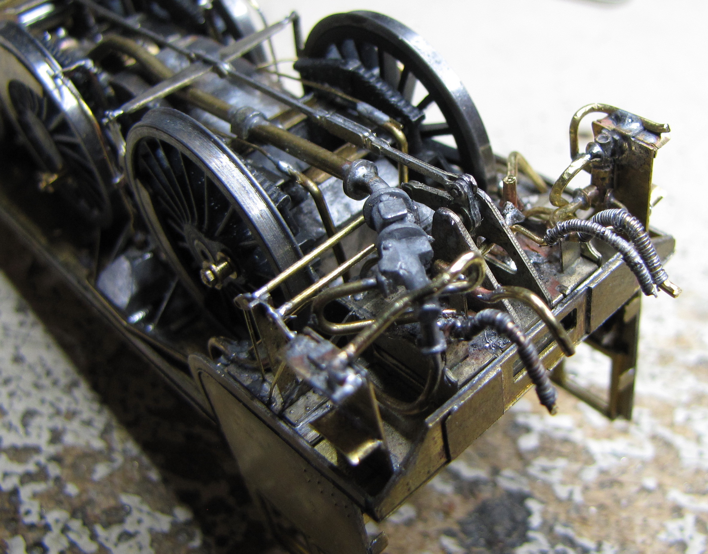
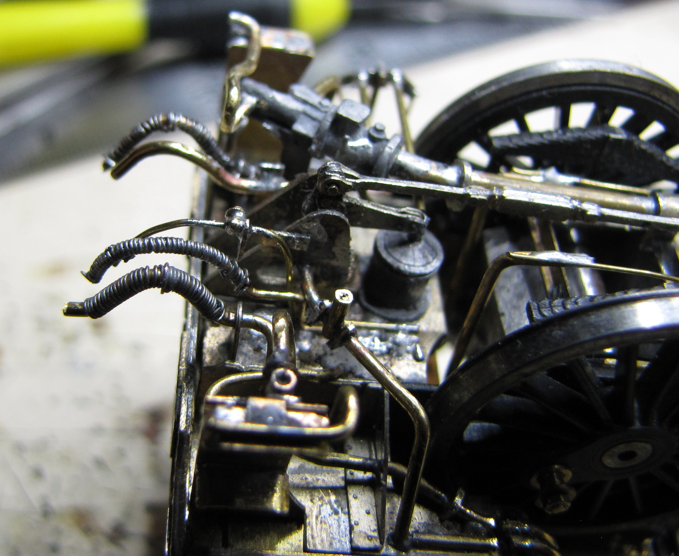
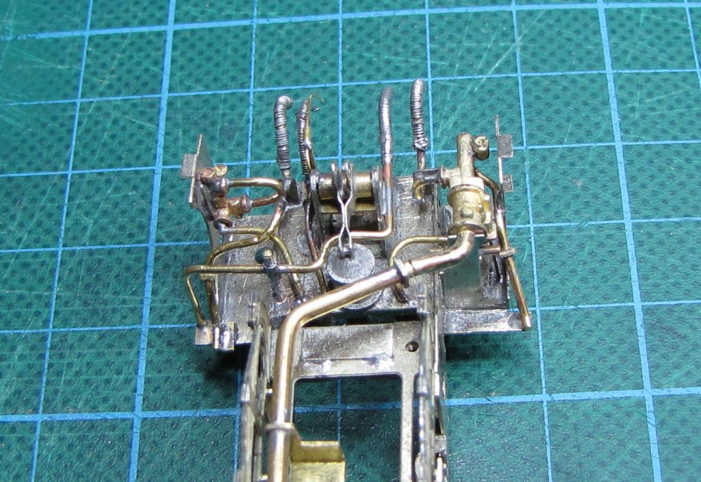
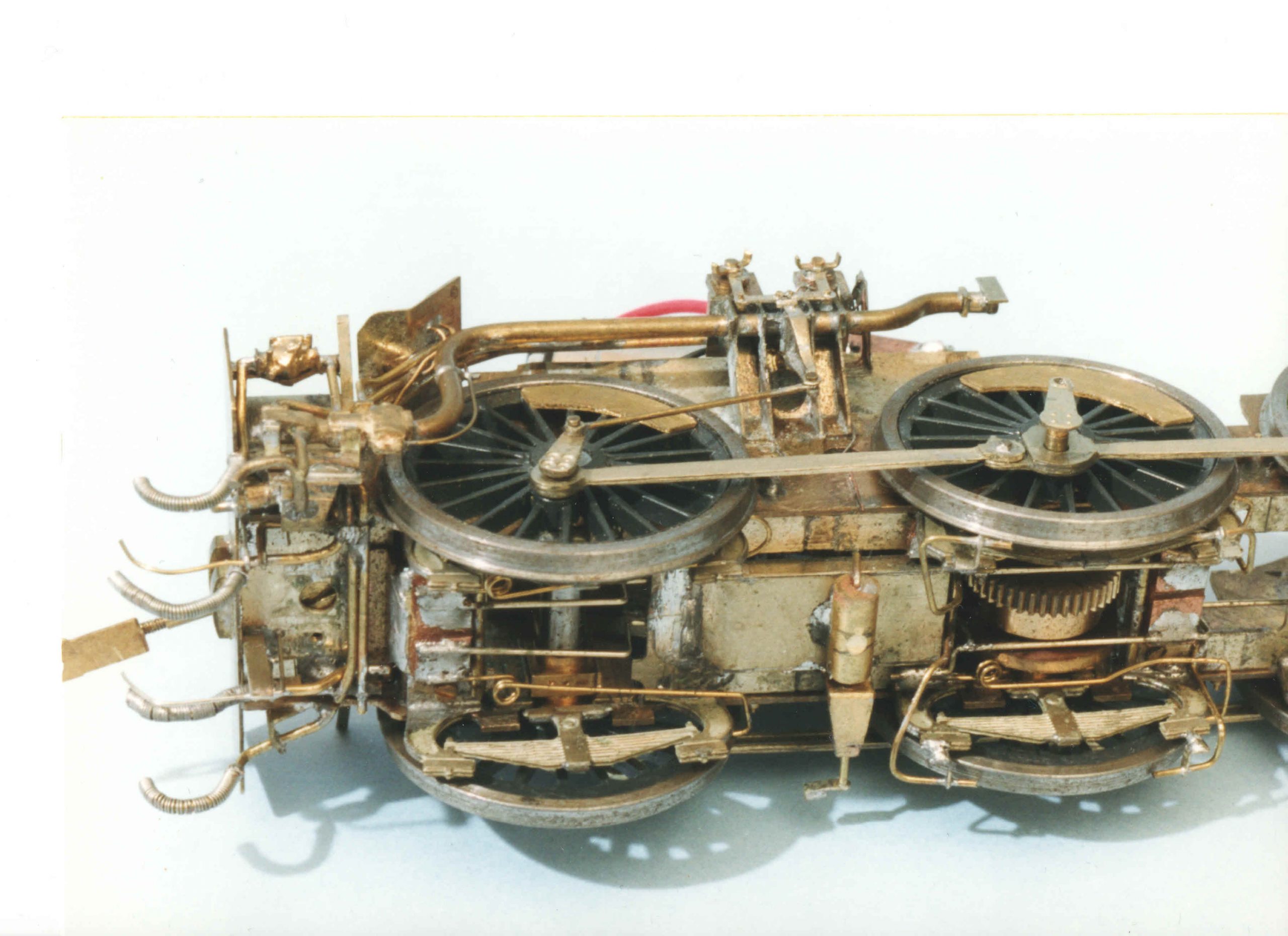
Pipework under the cab of the tender locos is extensive and quite complex. I like to represent all the major and some of the minor pipes and hoses which, even if not clearly visible on the completed model, do, in my mind at least, contribute to the overall feeling of bulk and solidity.
This extent of detail is only really possible if the appropriate GA and Pipe & Rod drawings are available, supplemented by photographs. I’m lucky in that respect because the various Wild Swan loco profiles include these drawings. The pipework is made from wire and tube in a variety of diameters. Ribbed hoses are rather crudely represented by winding 0.2 mm copper fuse wire round a pre-shaped wire core. The close-up photos are a bit cruel and the hoses don’t look too bad, especially when painted, in the gloom between loco and tender.

Aspects of Valve Gear
Where outside Walschaerts valve gear is required, kits usually provide a set of etched rods and basic slide bar and valve gear support brackets, to enable a reasonable representation to be assembled. However, the support brackets tend to be very basic and lack the webs and fillets that give the required strength and rigidity needed on the full size loco. I try to supplement the kit parts to better represent what should be there. Also, I prefer to model the valve gear in a short cut off forward gear position to give some movement to the radius rods. With Comet kits, this necessitates a second valve gear etch and modification of the reversing arrangements. The remainder of the un-used etch is a useful source of spare parts and rod ends.
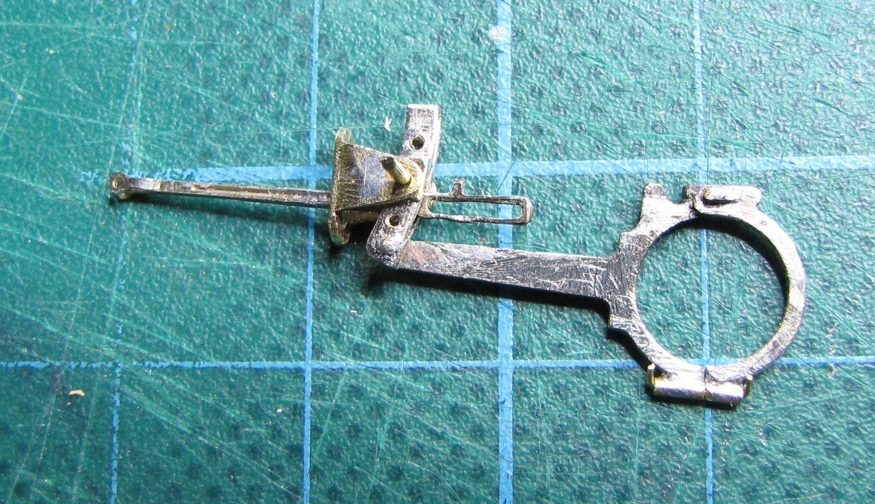
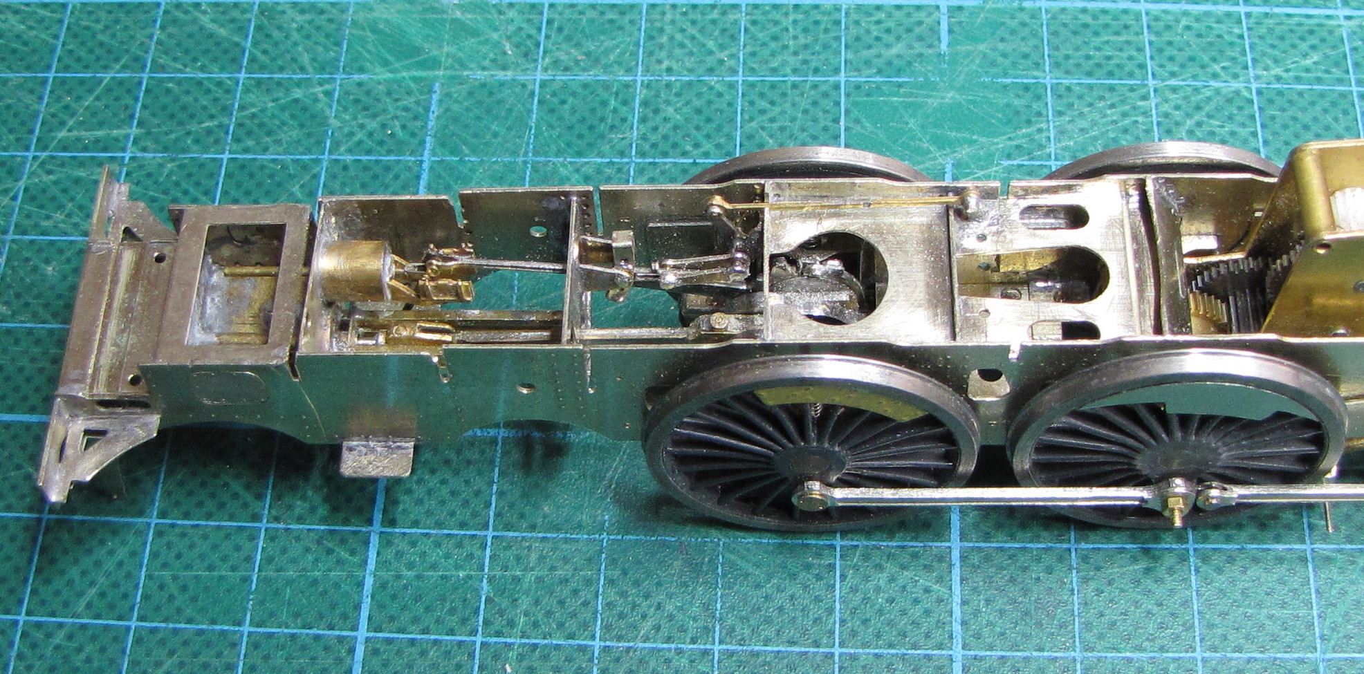
An aspect not usually covered in kits is that of inside valve gear, although there are kits that include either dummy or working inside gear, just not for the prototypes I’m interested in.
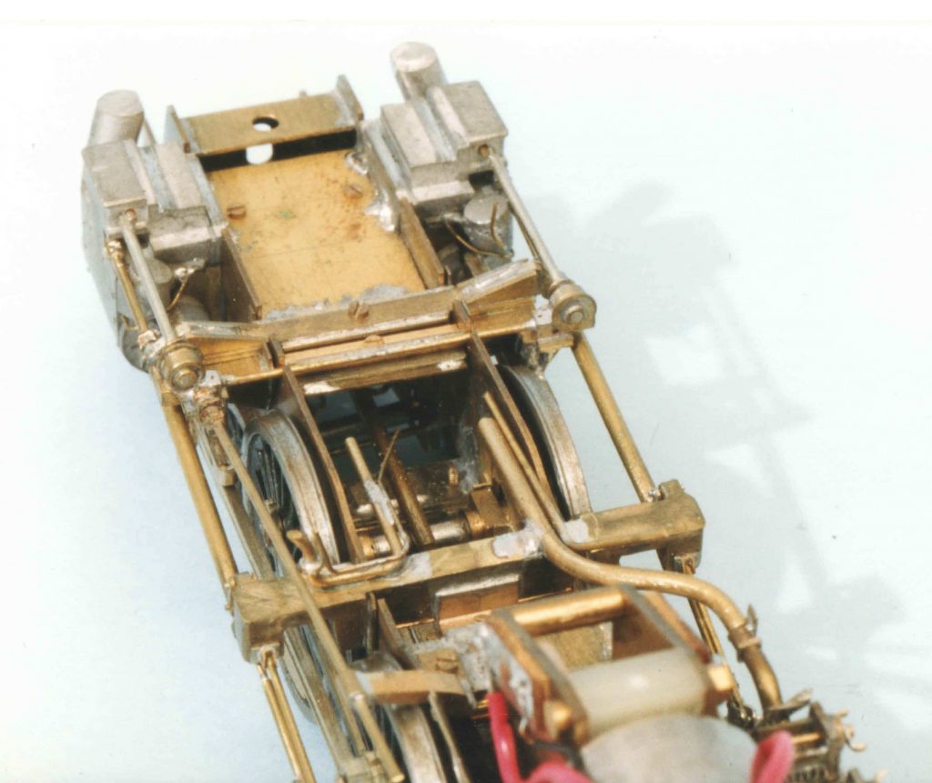
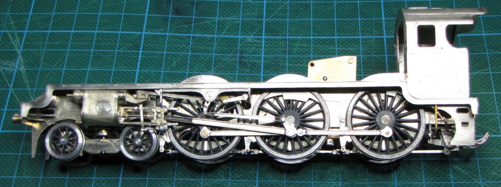
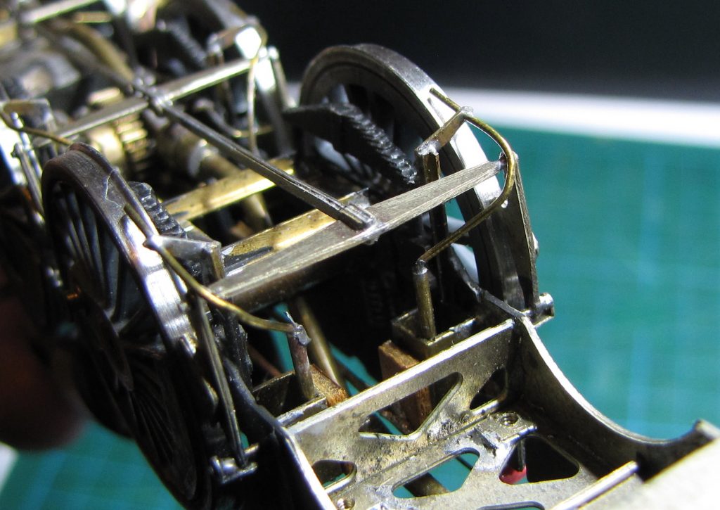
On the re-built Royal Scot, I’ve attempted to represent the inside valve gear even though it will be barely visible on the finished model. Most of the rods for the gear have been made by modifying parts from the Brassmasters Fowler 4F valve gear kit plus a few spare bits from a Black 5 kit. The crank webs are home made and the axle and crank pin holes were drilled on an industrial sized pillar drill, in the machine shop at the GWSR, where I work as a volunteer – the only use of a machine tool on this project.


Finally, I’d like to deal with outside Caprotti valve gear. A bit niche but a favourite of mine, perhaps prompted by a close encounter with a Caprotti Standard Class 5 at Manchester Exchange in the dying days of BR steam.
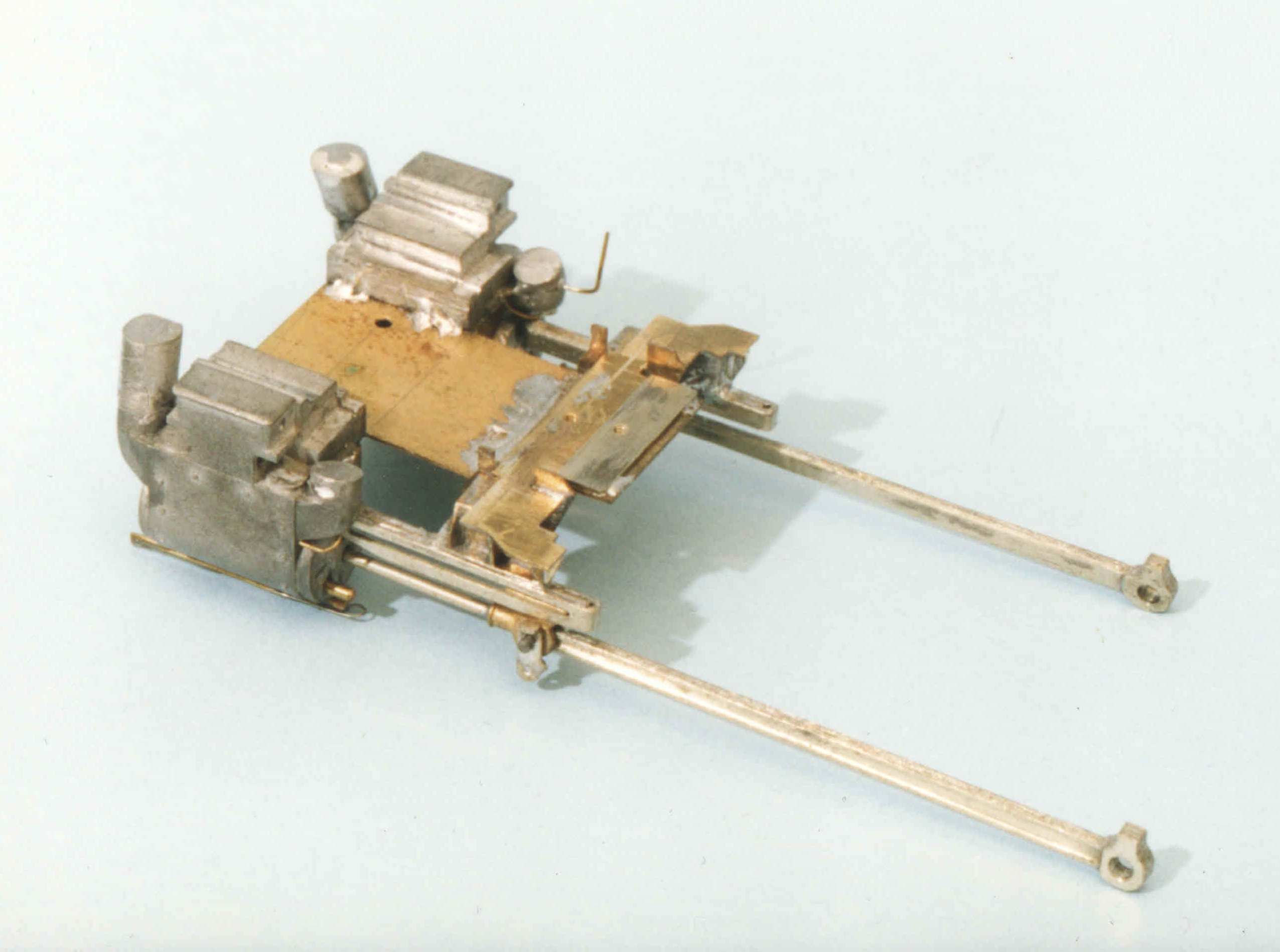
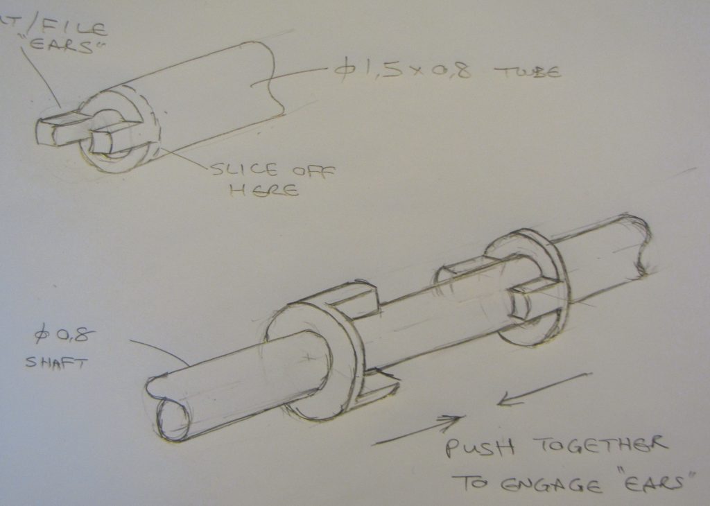
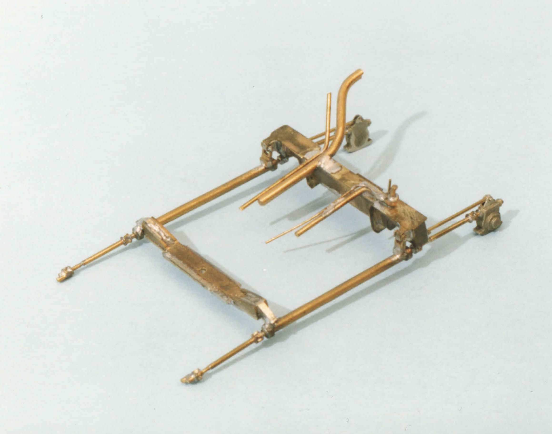
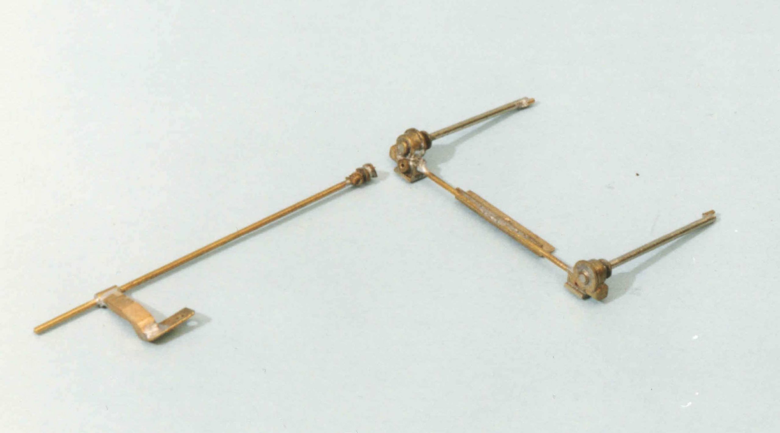
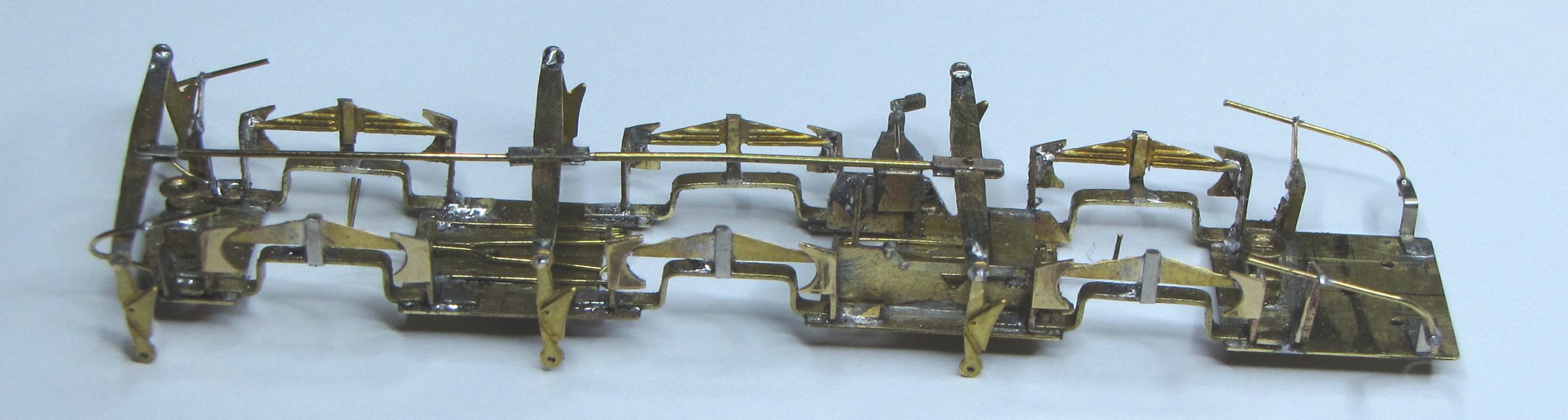
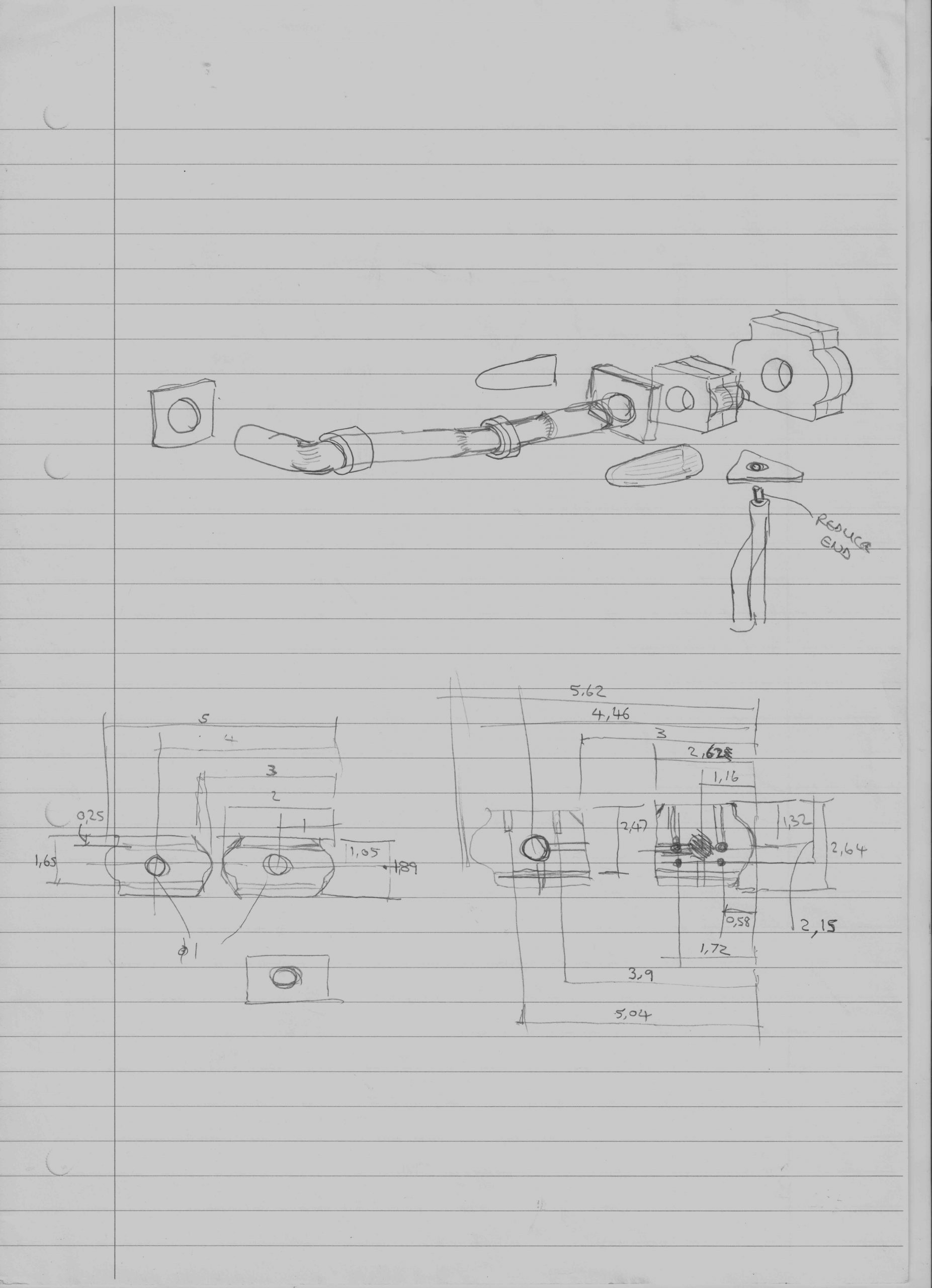
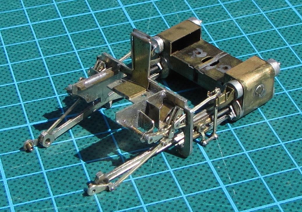
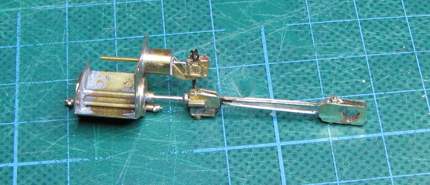
My model is based around a DJH kit which purported to provide cast N/S valve gear shafts. There was no provision of the support brackets for the shafts or slide bars. Also, the cast shafts proved to be incorrect in the lengths of the various sections and had no recognisable representation of the Hardy-Spicer type universal joints. The return crank gearboxes, on the end of the shafts, were a delight. I had done a dimensional survey and taken detailed photos of the valve gear on 73129 at Butterley, long before it was restored. This information proved invaluable.
I broke the gear down into a number of sub-sections to facilitate construction and painting, the various layers being fixed together with 14 BA screws.